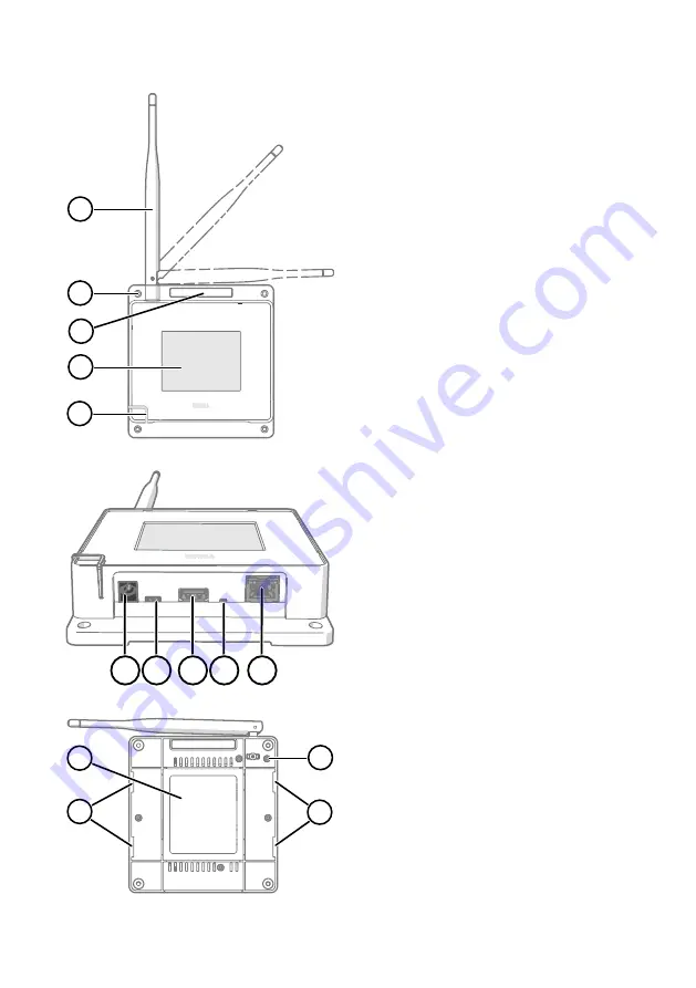
AP10 parts
1
2
3
4
5
Figure 4 Front
1
Antenna. Can be rotated and tilted.
2
Screw holes for mounting (4 pcs),
Ø 3.2 mm
3
Ventilation hole (do not cover)
4
Touchscreen
5
Status LED:
Green
Normal operation
Blue
Installation mode active
Red
Error - check status
1
2
3
4
5
Figure 5 Connector panel
1
Power supply connector
(10 ... 30 VDC)
2
Service port (micro-USB)
3
USB port for hardware expansion
(USB type A)
4
Reset button. Push to restart, push
and hold to revert AP10 to factory
settings.
5
RJ-45 Ethernet port. Can be powered
by Power over Ethernet (PoE).
1
2
2
3
Figure 6 Rear
1
Product label
2
Holes for mounting with tie wraps
3
Housing screws (do not remove)
12
M211821EN-E
Summary of Contents for VaiNet AP10
Page 1: ...EN DE FR ES PT JA ZH M211821EN E Quick Guide Vaisala VaiNet Wireless Access Point AP10...
Page 3: ...Table of contents English 5 Deutsch 15 Fran ais 25 Espa ol 35 Portugu s 45 55 65 3...
Page 4: ...4 M211821EN E...
Page 14: ......
Page 24: ......
Page 34: ......
Page 44: ......
Page 54: ......
Page 57: ...5 viewLinc Enterprise Server NTP Network Time Protocol NTP NTP UDP 123 AP10 NTP NTP NTP 15 57...
Page 58: ...AP10 B A 31 AP10 A 2 B 4 mm 116 124 3 50 32 AP10 1 AP10 2m 58 M211821EN E...
Page 63: ...japan support vaisala com www vaisala com support www vaisala com warranty 63...
Page 64: ......
Page 65: ...AP10 2 3 1 1 2 EMC 3 AP10 viewLinc NTP Internet AP10 NTP 1 AP10 viewLinc 2 a AP10 b 65...
Page 67: ...5 viewLinc NTP NTP NTP Internet UDP 123 AP10 NTP NTP NTP 15 67...
Page 68: ...AP10 B A 37 AP10 A 2 B 4 mm 116 124 3 50 38 AP10 1 AP10 2 6 2 68 M211821EN E...
Page 73: ...helpdesk vaisala com www vaisala com support www vaisala com warranty 73...
Page 74: ......
Page 75: ......
Page 76: ...www vaisala com...


