background image

Val Avionics Ltd 

AP 100 Audio Panel 

Installation and Operator’s Manual 

2.4  POST INSTALLATION CHECK 


2.4.1 Operational 

Check 


Switch on Aircraft Master and Avionics Master as appropriate. 


Power on the unit by pressing the ‘PWR’ switch. The blue LED should 
illuminate. 


Plug headset into jackset 


Select COM 1 by pressing the ‘COM 1’ XMT SEL’ switch. The green LED will 
illuminate. If the LED is flashing, stop testing and troubleshoot the microphone 
PTT installation. A flashing indicator in the COM select button indicates that the 
key line is grounded.  


Verify proper transmit and receive operation on the NO. 1 COM. Note that the 
LED flashes during the transmit function.  


Select COM 2 by pressing the ‘COM 2’ XMT SEL’ switch. The green LED will 
illuminate. Note that the LED flashes during the transmit function.  


Press the ‘BOTH’ button and verify that COM 1 and COM 2 receive audios can 
be heard. Note that the button stays in and the LED illuminates.  


Verify proper operation of the NAV 1 and NAV 2 receiver sources by selection 
them using the ‘NAV 1’ and ‘NAV 2’ buttons. Note that the button for the 
receiver source stays in and the LED illuminates to show which source is in use.  


Push in the ‘SPKR’ button to activate the cabin speaker and verify that the 
selected audio source can be heard over the cabin speaker. Verify that the speaker 
is muted when a transmitter is keyed. 


Press the ‘MKR MUTE’ button and verify that the marker audio is muted and that 
the LED indicator flashes for approximately 20 seconds. The LED indicator will 
then go steady again and the marker audio can be heard.  


Verify that the AP 100 Audio Panel does not adversely affect any other aircraft 
system by systematically switching the unit on and off while monitoring the other 
avionics and electrical equipment on the aircraft.  


2.4.2 Final 

Inspection 

 
Verify that the wiring is bundled away from all controls and that no part of the 
installation interferes with the movement of the aircraft controls. Move all of the aircraft 
controls through their full range of movement while visually verifying that the 
installation does not mechanically interfere with the control movement. Verify that the 
wiring harnesses are properly secured to the aircraft structure in accordance with 
accepted practices as described in AC 43.13 and that adequate strain relief and service 
loops have been provided. Ensure that there are no kinks or sharp bends in the wire 
harnesses. Verify that the wire bundles are not exposed to any sharp or abrasive surfaces. 

P/N 0720100 


Page 6 


Original Issue 


December 06 


Summary of Contents for AP 100

Page 1: ...VAL AVIONICS LTD AP 100 AUDIO PANEL Audio Management System Installation and Operator s Manual Original Issue October 06 P N 0720100 ...

Page 2: ... 5 2 3 3 Wire Harness Fabrication 5 2 3 4 Audio Panel Installation 5 2 4 POST INSTALLATION CHECK 6 2 4 1 Operational Check 6 2 4 2 Final Inspection 6 2 5 LIMITATIONS 7 3 SECTION III OPERATION 8 3 1 GENERAL INFORMATION 8 3 1 1 Scope 8 3 1 2 Transmit Selection 8 3 1 3 Audio Selection 8 4 SECTION IV WARRANTY AND SERVICE 10 4 1 WARRANTY 10 4 2 SERVICE 11 5 Appendix A INSTALLATION DRAWINGS AND CONNECTO...

Page 3: ...and Operator s Manual Table of Tables Pg Table 1 Specifications 2 Table 2 Equipment Supplied 3 Table 3 Equipment Not Supplied 3 Revision History Rev Date Description of change IR September 2006 Initial Release P N 0720100 ii Original Issue October 06 ...

Page 4: ...een designed for simplicity It is straight forward to install and operate Using state of the art technology Val Avionics has created an Audio Panel that will provide the pilot with simple unencumbered control of the various audio sources commonly found in today s civil aircraft The COM 1 COM 2 XMT SEL switches make it easy to select a transceiver for transmitting and receiving radio communications...

Page 5: ...dio source which would commonly be routed to the aircraft headphone and cabin speaker systems A Fail safe feature has been incorporated into the design of the AP 100 that will automatically connect the pilot s headphones and microphone to the aircrafts COM 1 radio in the event that power is removed from the audio Panel or if the unit is powered down 1 4 SPECIFICATIONS Table 1 Specifications DIMENS...

Page 6: ...pplied QTY DESCRIPTION PART NUMBER 1 Interconnect Wire Harness VPN 0751005 or field fabricated 1 Microphone Jacks Switchcraft P N S12B Ref VPN 550018 1 Headphone Jacks Switchcraft P N 11 Ref VPN 550017 1 Circuit Breaker 2 amp Potter Brumsfield W58 2 Ref VPN 0331005 1 Aircraft Cabin Speaker Ref aircraft parts manual for specific part number 1 Contact Crimping Tool w Positioning Tool AMP P N 601966 ...

Page 7: ...any hours of time and frustration 2 2 UNPACKING AND INSPECTION Use care when unpacking the equipment Inspect the unit and supplied parts for visual signs of damage during shipment Examine the unit for loose screws dents broken buttons and other signs of damage that may have occurred during shipment Verify the contents of the container with the list in section 1 5 If any damaged or missing parts ar...

Page 8: ... Wire Harness ordering information Although strongly recommended it is not required to use the factory fabricated wire harness when installing the AP 100 Audio Panel A wiring harness can be fabricated in the field Refer to appendix B of this manual for a complete wiring diagram All wires must be 22 AWG MIL SPEC unless otherwise noted in accordance with current regulations Two and three conductor s...

Page 9: ...the SPKR button to activate the cabin speaker and verify that the selected audio source can be heard over the cabin speaker Verify that the speaker is muted when a transmitter is keyed Press the MKR MUTE button and verify that the marker audio is muted and that the LED indicator flashes for approximately 20 seconds The LED indicator will then go steady again and the marker audio can be heard Verif...

Page 10: ...7 weight and balance computations and other documentations as required 2 5 LIMITATIONS There are no known limitations to the operation of the AP 100 Audio Panel Instructions for Continued Airworthiness and Return to Service Instructions can be found in Appendix C P N 0720100 Page 7 Original Issue December 06 ...

Page 11: ...rting the pilot that the selected transmitter is active Only one transmitter can be selected at any time With the unit turned off the pilot s microphone and head set are automatically connected to COM 1 3 1 3 Audio Selection Received audio from both COM 1 and COM 2 can be routed to the headphones as desired by activating the BOTH switch When both audios are selected an LED annunciation will illumi...

Page 12: ...elect switch Doing so will mute the incoming marker audio for approximately 20 seconds While the marker audio is muted the MKR LED annunciator will flash Four un switched audio inputs are provided at the rear connector for such audio inputs as DME ADF Auto Pilot alerts or any other audio source which would commonly be routed to the aircraft headphone and cabin speaker systems These audios are not ...

Page 13: ...ctions accident or negligent damage alterations of any manner and repair by other than the factory the repairs will not be covered under the warranty In such cases an estimate will be submitted for approval before repair is initiated In most cases Val avionics Ltd will provide 72 hour turn around on its warranty and repair service We recommend that contact be made with the FACTORY CUSTOMER SERVICE...

Page 14: ...lity Units in need of servicing should be returned prepaid to Val Avionics Ltd at the following addresses If you are shipping by the US Postal Service address To Val Avionics P O Box 13025 Salem OR 97309 If you are shipping by Fedex UPS or other shipping company address To Val Avionics 3280 25th ST SE Salem OR 97302 P N 0720100 Page 11 Original Issue December 06 ...

Page 15: ...udio Panel Installation and Operator s Manual 5 Appendix A INSTALLATION DRAWINGS AND CONNECTOR LAYOUT 54 36 5 83 6 80 6 34 1 00 Figure 3 Physical Dimensions Figure 4 Panel Cut Out P N 0720100 Page 12 Original Issue December 06 ...

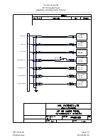
Page 16: ...Out Com 1 Mic Key Out Mic Audio Mic Key COM 2 Audio GND Mic GND Cabin Speaker Cabin Speaker Out Aircraft Mic Return Aircraft Mic Audio In Aircraft Mic Key In Com 1 Phone Return Aircraft Phone Return Aircraft Phone Out Com 2 Mic Key Out Com 2 Mic Audio Out Com 2 Phone Return Com 2 Phone Audio In Phone Audio Out Phone Audio Out To Intercom System Avionics Bus B Avionics Bus B Aircraft Ground Aircraf...

Page 17: ...NAV 2 Audio Gnd Audio Out NAV 1 Audio Gnd Audio Out Audio Gnd AUTO PILOT Audio Out Audio Gnd Audio Out DME Audio Gnd Audio Gnd Audio Out Unswitched Audio 4 Unswitched Audio 1 Unswitched Audio 3 Unswitched Audio 2 Marker Audio Nav 2 Audio NOTE 6 Nav 1 Audio J1 TAS ADF P N 0720100 Page 14 Original Issue December 06 ...

Page 18: ...TINUED AIRWORTHINESS 7 1 MAINTENANCE INSTRUCTIONS Maintenance of the AP 100 is on condition only No periodic maintenance is required If unit is removed for service upon re installation perform Post Installation check as described in section 2 4 of this manual P N 0720100 Page 15 Original Issue December 06 ...

Reviews: