background image

®

L2694

Rev. B

10/06

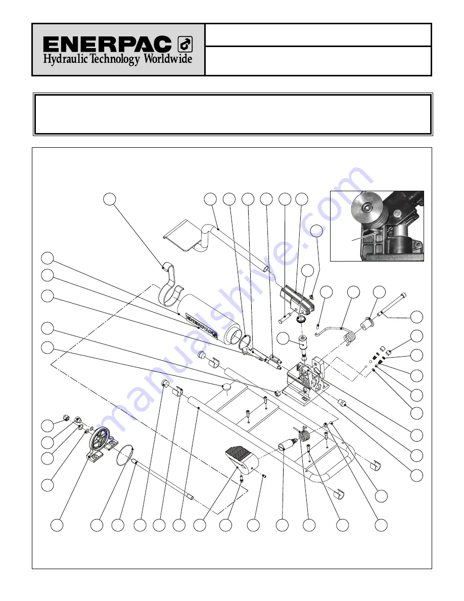
For Date Codes beginning with the Letter "A"

Item 14: 

Set relief valve at 700 bar [10,000 psi] max. 
Torque to 14-16 Nm [10-12 Ft. lbs]

Item 16: 

Set by-pass valve to 14-19 bar [200-275 psi] max. 
Torque to 14-16 Nm [10-12 Ft. lbs]

Item 30: 

Torque to 20 Nm [15 Ft. lbs]

9

11

3

15

16

43

7

17

36

37

38

39

41

35

1

6

5

13

25

27

10

22

33

34

19

23

21

40

28

29

32

30

26

31

14

12

4

39

Item
24:

Spring
Tab
Position

44

24

42

8

45

18

2

To Protect Your Warranty, Use Only ENERPAC Hydraulic Oil.

Enerpac recommends that all kit components be installed to insure optimum performance of the repaired unit.

Repair Parts Sheet

P-392FP

700 Bar Foot Pump

Summary of Contents for VIPER QS-1800A

Page 1: ...G THE QS 1800A INJECTING MATERIAL IN YOUR VALVE PERIODIC MAINTENANCE FOR YOUR PUMP HYDRAULIC PUMP PERIODIC MAINTENANCE EIS 63 107 1 HYDRAULIC PUMP REPAIR PARTS SHEET l2694 Rev B RETROFIT KIT NEEDED FOR REPAIR ONLY L2695 Rev A MATERIAL SAFETY DATA SHEET HYDRAULIC FLUID ...

Page 2: ... 52752 1 2 1 2 27 Z SWIVEL 1 1819 HYDRAULIC TUBING 1 PT 1 4 x 375 1 4 NPTx 375 TUBE FITTING 1 PT 3 8 x 375 3 8 NPTx 375 TUBE FITTING 1 2018 GREASE BARREL ASSEMBLY 1 CONSISTS OF 1407 GREASE BARREL CAP 2 1409 R GREASE BARREL 1 1410 O RING 2 1413 HANDLE TAG METAL TAG 2008 PISTON ASSEMBLY 1 CONSISTS OF 1408 A CAP SCREW 1 1408 BA COPPER WASHER 1 2008 1 PISTON BODY 1 2008 2 SNAP RING 2 2008 3 RETAINING ...

Page 3: ...lied remove sealant barrel cap 1407 3 Depress and hold bypass pedal in release position to allow you to return the piston assembly 4 Use the handle 1413 to push piston assembly 2008 to the desired depth When less than full capacity is required use 1 oz marking on handle 5 Release foot pedal 6 Load Val Tex lube sealant or Valve Flush as required Remember to remove cellophane wrapper on sticks ...

Page 4: ...DURE COULD RESULT IN SERIOUS INJURY THE SEALANT CAP MUST BE COMPLETELY SCREWED ONTO THE BARREL BEFORE OPERATING THIS UNIT THE YELLOW SAFETY GAUGE MUST BE LIFTED UP AND THE BOTTOM SIDE OF THE TAB MUST CLEAR THE TOP OF THE CAP 8 Place foot on the foot pedal Then remove the handle retainer to allow you to pump the unit SAFE STOP ...

Page 5: ...l cap 1407 is removed the piston assembly 2008 can be pumped out of the cylinder Dispose of any expelled material properly Injecting Material Into Your Valve 1 The gun is equipped to couple onto a giant buttonhead fitting 2 Monitor the gauge during pumping to avoid excessive pressure 3 It takes approximately 11 strokes to inject 1 ounce of material Periodic Maintenance For Pump Refer to the Enerpa...

Page 6: ...ting the load Never use a hydraulic cylinder as a shim or spacer in any lifting or pressing application DANGER To avoid personal injury keep hands and feet away from cylinder and workpiece during operation WARNING Do not exceed equipment ratings Never attempt to lift a load weighing more than the capacity of the cylinder Overloading causes equipment failure and possible personal injury The cylinde...

Page 7: ...il to the reservoir than it is capable of holding 4 0 INSTALLATION 4 1 Connecting the Pump 1 Thread hose into pump outlet Use 1 1 2 wraps of Teflon tape or suitable thread sealant on hose fitting leaving the first complete thread free of tape to ensure that tape does not shed into hydraulic system causing damage Trim loose ends 2 Install a pressure gauge in line from the pump for added safety and ...

Page 8: ...ing pull cylinder See Figure 4 below 4 Operate pump to fully extend the cylinder retract if using pull cylinder 5 Open release valve to retract cylinder extend if a pull cylinder This will force the trapped air to move up to the pump reservoir 6 Repeat the above steps as necessary 7 Add oil if necessary See paragraph 7 1 page 3 8 Return vent fill cap to operating position 7 0 MAINTENANCE Use only ...

Page 9: ...Pump reservoir is over filled 3 Loose hydraulic coupler 4 Air trapped in system 5 Hose internal diameter too narrow 6 Cylinder retraction spring broken or other cylinder damage 1 Open release valve 2 Drain oil level to full mark See page 3 instructions for adding oil paragrapg 7 1 3 Check that all couplers are fully tightened 4 Remove air according to the instructions on page 3 paragraph 6 0 5 Use...

Page 10: ...16 Nm 10 12 Ft lbs Item 30 Torque to 20 Nm 15 Ft lbs 9 11 3 15 16 43 7 17 36 37 38 39 41 35 1 6 5 13 25 27 10 22 33 34 19 23 21 40 28 29 32 30 26 31 14 12 4 39 Item 24 Spring Tab Position 44 24 42 8 45 18 2 To Protect Your Warranty Use Only ENERPAC Hydraulic Oil Enerpac recommends that all kit components be installed to insure optimum performance of the repaired unit Repair Parts Sheet P 392FP 700...

Page 11: ...sia Tel 7 495 9809091 Fax 7 495 9809092 Singapore Actuant Asia Pte Ltd 25 Serangoon North Ave 5 03 01 Keppel Digihub Singapore 554914 Thomson Road P O Box 114 Singapore 915704 Tel 65 64 84 5108 65 64 84 3737 Fax 65 64 84 5669 Toll Free 1800 363 7722 Technical Inquiries techsupport enerpac com sg South Korea Actuant Korea Ltd 3Ba 717 Shihwa Industrial Complex Jungwang Dong Shihung Shi Kyunggi Do Re...

Page 12: ...ng reassembly 2 0 REASSEMBLY 1 Place the spring spacer 42 and return spring 24 around the new beam pin 18 from the kit 2 Slide the beam pin 18 through the holes in the pump base 1 and the pump handle assembly 11 Continue until the pin end slides through the hole on opposite side of pump base N No ot ti ic ce e During reassembly be sure that return spring tab is inserted into the pump base cavity a...

Page 13: ...No 9 10 11 Plot No 56 Monarch Plaza Sector 11 C B D Belapur Navi Mumbai 400614 India Tel 91 22 2756 6090 Tel 91 22 2756 6091 Fax 91 22 2756 6095 Italy ENERPAC S p A Via Canova 4 20094 Corsico Milano Tel 39 02 4861 111 Fax 39 02 4860 1288 Japan Applied Power Japan Ltd Besshochou 85 7 Saitama shi Kita ku Saitama 331 0821 Japan Tel 81 48 662 4911 Fax 81 48 662 4955 Middle East Turkey and Caspian Sea ...

Page 14: ......

Page 15: ......

Page 16: ......

Page 17: ......

Reviews: