background image

8

EN

Using the appliance

B

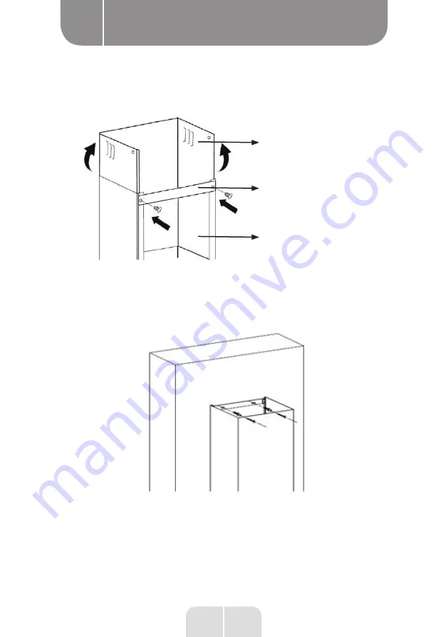
Upper decorative chimney (Inner)

Lower Chimney bracket

Lower decorative chimney (Outer)

Put the chimney on the cooker hood. Fix the lower chimney bracket on the wall by 2 screws(4mm 
x30mm). 

Then pulling out the upper chimney upwards to the target height. Adjust to reach the height required.

Fix the upper chimney on the upper chimney bracket by 2 screws (4x8mm). Then fix the upper 
chimney bracket on the wall. Before fixing the bracket on the wall, you can decide the upper 
chimney bracket fixing holes for installation.

Summary of Contents for 974840

Page 1: ......

Page 2: ...male du produit sur présentation du ticket de caisse NL GARANTIEVOORWAARDEN Dit product wordt gegarandeerd voor een periode van 2 jaar vanaf de aankoopdatum voor elke storing die het gevolg is van een fabricagefout of het materiaal Gebreken of schade door slechte installatie onjuist gebruik of abnormale slijtage van het product worden niet gedekt door deze garantie op vertoon van kassabon ES CONDI...

Page 3: ...974840 FIH 60 EGK 756C v4 974861 FIH 90 EGK 756C v4 Extractor hood Hotte aspirante Dampkap Campana extractara INSTRUCTIONS FOR USE 02 CONSIGNES D UTILISATION 16 GEBRUIKSAANWIJZINGEN 30 INSTRUCCIONES DE USO 44 2 2 ...

Page 4: ......

Page 5: ...1 4 2 5 3 ...

Page 6: ......

Page 7: ......

Page 8: ......

Page 9: ...tested and recommended by ELECTRO DEPOT the products of the VALBERG brand are easy to use reliable and of an impeccable standard Thanks to this appliance you can be sure that each use will bring you satisfaction Welcome to ELECTRO DEPOT Visit our website www electrodepot fr ...

Page 10: ...ts A Preview of the appliance C Useful information B Using the appliance Wall mounting installation Installation without external opening Replacement the lamp Maintenance of the appliance Troubleshooting Description of the appliance ...

Page 11: ...ton For decreasing the speed of the fan 3 Digital display Fan speed display 1 for Low speed 2 for Medium speed 3 for High speed 4 Speed plus button For increasing the speed of the fan 5 Light button BOOSTER FUNCTION Press to speed 4 enter into highest speed while the hood is in use and it will increase speed for 5 minutes after that slowing down again ...

Page 12: ...er hood can be connected as below picture by means of an extraction duct enamel aluminum flexible pipe or inflammable material with an interior diameter of 150mm Before installation turn the unit off and unplug it from the outlet The cooker hood should be placed at a distance of 65 75cm above the cooking plane for best effect ...

Page 13: ...stallation of the cookerhood Drill 3 x 8 mm holes for hood holding bracket Tighten the bracket with the screws and plugs provided Wall holes Screw plug Wallbracket 4 x 30 mm screw Lift the hood up and hang it onto the wall bracket ...

Page 14: ...r the installation from the inside of the hood Take the hood back down again Drill the four ø 8 mm holes at the marked locations Insert four wall plugs into the holes and four screws into the wall Hang the extractor hood back in the wall bracket and tighten the four screws on the inside of the extractor hood ...

Page 15: ...y bracket on the wall by 2 screws 4mm x30mm Then pulling out the upper chimney upwards to the target height Adjust to reach the height required Fix the upper chimney on the upper chimney bracket by 2 screws 4x8mm Then fix the upper chimney bracket on the wall Before fixing the bracket on the wall you can decide the upper chimney bracket fixing holes for installation ...

Page 16: ...9 EN Using the appliance B Fix the lower chimney with 2 pcs of 4x8mm screws on the cooker hood ...

Page 17: ... safety reason please use only the same size of fixing or mounting screw which are recommended in this instruction manual Warning Failure to install the screws or fixing device in accordance with these instructions may result in electrical hazards ...

Page 18: ...outlet and attach it in place by turning it anticlockwise Installing the active carbon filter cut out The metal filter has to be removed before the active carbon filter is installed To open the metal filter press on the locking device and pull the filter downwards Place the pre cut filter on top of the metal filter Hold it in position using the metal rods supplied depending on the model Replace th...

Page 19: ...ght source in this product can only be replaced by qualified professionals Please contact after sales service if the light source fails The light source shall be removed at the end of the product s useful life with sorting and recycling done separately ...

Page 20: ...m de M10 moer Nut bij A 3 Keer dezelfde bewerking uit voor de andere kant in B OPMERKING Het glazen gedeelte mag bij normaal gebruik niet worden geopend het mag alleen worden geopend voor reiniging en onderhoud ES ERRATA INSTRUCCIONES DE USO Mantenimiento del dispositivo Reapriete de las tuercas del soporte de tope 1 Abra la parte superior de vidrio 2 Use una llave M10 Spanner para apretar la tuer...

Page 21: ...lug in to the power supply again Serious Vibration of the unit The fan blade is damaged Switch of the unit and repair by qualified service personnel only The fan motor is not fixed tightly Switch of the unit and repair by qualified service personnel only The unit is not hung properly on the bracket Take down the unit and chack whether the bracket is in proper Suction performance not good Too long ...

Page 22: ...15 EN Note ...

Page 23: ...EPOT les produits de la marque VALBERG sont simples d u t i l i s a t i o n t o u t e n o f f ra n t d e s p e r fo r m a n ce s fiables et une qualité irréprochable Grâce à cet appareil vous êtes assuré e que chaque utilisation vous apportera satisfaction Bienvenue chez ELECTRO DEPOT Consultez notre site Internet www electrodepot fr www electrodepot be ...

Page 24: ...les B Utilisation de l appareil Les instructions sont également disponibles sur le site http www electrodepot fr sav notices http www electrodepot fr sav notices Montage mural Installation sans ouverture vers l extérieur Remplacement de l ampoule Maintenance de l appareil Dépannage Description de l appareil ...

Page 25: ...e Affichage de la vitesse de la hotte 1 correspond à une vitesse faible 2 à une vitesse moyenne et 3 à une vitesse élevée 4 Bouton d augmentation de la vitesse Il permet d augmenter la vitesse de la hotte 5 Bouton d éclairage FONCTION BOOSTER Appuyez sur pour atteindre la vitesse 4 entrez dans la vitesse la plus élevée pendant que la hotte est utilisée et elle augmentera la vitesse pendant 5 minut...

Page 26: ...indiquée dans l illustration ci dessous au moyen d un conduit d extraction tuyau flexible en aluminium émail ou autre matériau non inflammable d un diamètre intérieur de 150 mm Avant toute installation éteignez l appareil et débranchez le de la prise de courant Pour un résultat optimal la hotte aspirante doit être installée à une distance de 65 à 75 cm au dessus de la surface de cuisson ...

Page 27: ...ation de la hotte aspirante Percez 3 trous de 8 mm pour le support de la hotte Fixez le support à l aide des vis et chevilles fournies Trous muraux Chevilles Support mural Vis de 4 x 30 mm Soulevez la hotte et accrochez la sur le support mural ...

Page 28: ...l intérieur de la hotte pour les 4 trous nécessaires à l installation Décrochez la hotte Percez les 4 trous de 8 mm de diamètre au niveau des repères Insérez 4 chevilles murales et 4 vis dans les trous réalisés dans le mur Accrochez à nouveau la hotte aspirante sur le support mural et serrez les 4 vis depuis l intérieur de la hotte ...

Page 29: ...ieure Cheminée décorative inférieure extérieur Placez la cheminée sur la hotte aspirante Fixez le support de la cheminée inférieure au mur à l aide de 2 vis 4 mm x 30 mm Déployez ensuite la cheminée supérieure vers le haut jusqu à la hauteur souhaitée Ajustez la de manière à atteindre la hauteur requise ...

Page 30: ...rieure sur le support de la cheminée supérieure à l aide de 2 vis 4 x 8 mm Fixez ensuite le support de la cheminée supérieure au mur Avant de fixer ce support au mur vous pouvez déterminer la position des trous de fixation correspondants pour l installation ...

Page 31: ...s Avertissement pour des raisons de sécurité veuillez utiliser uniquement des vis de fixation ou de montage présentant les dimensions recommandées dans ce guide d utilisation Avertissement toute installation de vis ou de dispositifs de fixation non conforme aux présentes instructions peut entraîner un danger électrique ...

Page 32: ...ournant dans le sens inverse des aiguilles d une montre Installez le filtre à charbon actif à découper Pour installer le filtre à charbon actif le filtre métallique doit être préalablement retiré Pour ouvrir la filtre métallique appuyez sur le dispositif de verrouillage puis tirez le filtre vers le bas Placez le filtre pré découpé au dessus du filtre métallique Maintenez le en position à l aide de...

Page 33: ...des professionnels qualifiés Veuillez vous rapprocher du service après vente en cas de défaillance de la source lumineuse Il convient de retirer la source lumineuse à la fin de la vie utile du produit le tri et le recyclage étant effectués séparément PC Cache PC Réflecteur Ressort Unité mm Unité mm Surface en Acier Inoxydable ...

Page 34: ...10 moer Nut bij A 3 Keer dezelfde bewerking uit voor de andere kant in B OPMERKING Het glazen gedeelte mag bij normaal gebruik niet worden geopend het mag alleen worden geopend voor reiniging en onderhoud ES ERRATA INSTRUCCIONES DE USO Mantenimiento del dispositivo Reapriete de las tuercas del soporte de tope 1 Abra la parte superior de vidrio 2 Use una llave M10 Spanner para apretar la tuerca M10...

Page 35: ...imentation L appareil présente des vibrations importantes La pale du ventilateur est endommagée Éteignez l appareil et faites le réparer uniquement par un technicien de maintenance qualifié Le moteur de la hotte n est pas fixé correctement Éteignez l appareil et faites le réparer uniquement par un technicien de maintenance qualifié L appareil n est pas bien accroché sur le support Décrochez l appa...

Page 36: ...29 EN Notes ...

Page 37: ...ie gekozen getest en aanbevolen worden door ELECTRO DEPOT zijn eenvoudig te gebruiken betrouwbaar en van onberispelijke kwaliteit Dankzij dit toestel kunt u er zeker van zijn dat u bij elk gebruik volledig tevreden zult zijn Welkom bij ELECTRO DEPOT Bezoek onze website www electrodepot fr www electrodepot be ...

Page 38: ... 31 NL Inhoudstafel A Voorbeeldweergave van het toestel C Nuttige informatie B Het toestel gebruiken Montage aan de muur Installatie zonder opening naar buiten Vervangen van de lamp Onderhoud van het apparaat Probleemoplossing Beschrijving van het toestel ...

Page 39: ...lator te verminderen 3 Digitaal weergavescherm Weergavescherm voor de snelheid van de ventilator 1 voor Lage snelheid 2 voor Middelmatige snelheid 3 voor Hoge snelheid 4 Knop om de snelheid te verhogen Om de snelheid van de ventilator te verhogen 5 Lichtknop BOOSTER FUNCTIE Druk op om snelheid 4 in te stellen voer de hoogste snelheid in terwijl de kap in gebruik is en de snelheid zal gedurende 5 m...

Page 40: ...als weergegeven in onderstaande afbeelding door middel van een afzuigkanaal email aluminium flexibele slang of onontvlambaar materiaal met een binnendiameter van 150 mm Alvorens te installeren zet het toestel uit en maak het los van de uitlaat Voor het beste effect zou de afzuigkap op een afstand van 65 75cm boven het kookvlak moeten worden geplaatste ...

Page 41: ...tie van de afzuigkap Boor 3 gaten van 8 mm voor de houder van de afzuigkap Bevestig de houder met de meegeleverde schroeven en pluggen Gaten in de muur Schroefplug Muurhouder 4 x 30 mm schroef Til de afzuigkap op en hang ze op de muurhouder ...

Page 42: ...atie vanuit de binnenkant van de kap Neem de kap opnieuw van de houder Boor de vier gaten met een diameter van 8 mm op de gemarkeerde plaatsen Plaats de vier muurpluggen in de gaten en draai de vier schroeven in de muur Hang de afzuigkap opnieuw in de muurhouder en bevestig de vier schroeven op de binnenkant van de afzuigkap ...

Page 43: ...ant Onderste schouwhouder Onderste sierschouw Buitenkant Zet de Schouw op de afzuigkap Bevestig de onderste schouwhouder op de muur met 2 schroeven 4 mm x 30 mm Til de bovenste schouw naar boven tot de gewenste hoogte Pas aan om de vereiste hoogte te bereiken ...

Page 44: ...ste schouw op de bovenste schouwhouder met 2 schroeven 4 x 8 mm Bevestig vervolgens de bovenste schouwhouder op de muur Alvorens de houder op de muur te bevestigen kunt u beslissen waar de gaten moeten komen om de bovenste schouwhouder te bevestigen ...

Page 45: ...aarschuwing Gelieve om veiligheidsredenen enkel dezelfde grootte van bevestigings of montageschroeven te gebruiken zoals aanbevolen in de instructiehandleiding Waarschuwing Wanneer het toestel niet wordt bevestigd of vastgeschroefd in overeenstemming met deze instructies kan dit resulteren in elektrische risico s ...

Page 46: ...m vast door het tegen de klok in te draaien Installeer de actieve koolstoffilter uit te snijden Om de actieve koolfilter te installeren moet de metalen filter van tevoren worden verwijderd Om de metalen filter te openen drukt u op het slot en trekt u de filter naar beneden Plaats de vooraf uitgesneden filter boven de metalen filter Houd hem in positie met behulp van metalen stangen geleverd volgen...

Page 47: ...lificeerde professionals Neem contact op met de klantenservice als de lichtbron uitvalt De lichtbron moet aan het einde van de gebruiksduur van het product worden verwijderd waarbij de sortering en recycling afzonderlijk worden uitgevoerd Afdekplaat Reflector Veer Eenheid mm Oppervlak in roestvrij staal Eenheid mm ...

Page 48: ...de M10 moer Nut bij A 3 Keer dezelfde bewerking uit voor de andere kant in B OPMERKING Het glazen gedeelte mag bij normaal gebruik niet worden geopend het mag alleen worden geopend voor reiniging en onderhoud ES ERRATA INSTRUCCIONES DE USO Mantenimiento del dispositivo Reapriete de las tuercas del soporte de tope 1 Abra la parte superior de vidrio 2 Use una llave M10 Spanner para apretar la tuerca...

Page 49: ... de stekker opnieuw in het stopcontact Het toestel trilt hevig Het ventilatorblad is beschadigd Schakel het toestel uit en laat enkel door gekwalificeerd servicepersoneel herstellen De ventilatormotor is niet stevig bevestigd Schakel het toestel uit en laat enkel door gekwalificeerd servicepersoneel herstellen Het toestel is niet naar behoren op de houder opgehangen Demonteer het toestel en contro...

Page 50: ...43 EN Notities ...

Page 51: ... probado y recomendado por ELECTRO DEPOT los productos de la marca VALBERG son fáciles de usar fiables y de un estándar impecable Gracias a este aparato puede estar seguro de que cumplirá sus necesidades en cada uso Bienvenido a ELECTRO DEPOT Visite nuestra web www electrodepot es ...

Page 52: ...5 ES Índice A Vista previa del aparato C Información útil B Uso del aparato Instalación de montaje en pared Instalación sin abertura hacia el exterior Cambio de la bombilla Mantenimiento del dispositivo Solución de problemas Descripción del aparato ...

Page 53: ...elocidad del ventilador 3 Pantalla digital Pantalla de velocidad del ventilador 1 velocidad baja 2 velocidad media y 3 velocidad alta 4 Botón de aumento de velocidad Aumenta la velocidad del ventilador 5 Botón de luz FUNCIÓN BOOSTER Presione a la velocidad 4 entre en la velocidad más alta mientras la campana está en uso y aumentará la velocidad durante 5 minutos después de lo cual se reducirá de n...

Page 54: ...ctar como en la imagen de abajo mediante un conducto de extracción esmalte aluminio tubo flexible o material inflamable con un diámetro interior de 150 mm Antes de la instalación apague el aparato y desconéctelo de la toma de corriente La campana extractora debe colocarse a una distancia de 65 75 cm por encima del plano de cocción para obtener el mejor efecto ...

Page 55: ... 3 orificios de 8 mm para el soporte de sujeción de la cubierta de la campana extractora Fije el soporte con los tornillos y tacos incluidos Agujeros de pared Tornillo de fijación Soporte de pared 4 x 30 mm tornillo Levante la campana y cuélguela en el soporte de pared ...

Page 56: ...ón desde el interior de la campana Vuelva a bajar la cubierta Taladre los cuatro orificios de ø 8 mm en los lugares marcados Inserte cuatro tacos de pared en los orificios y cuatro tornillos en la pared Vuelva a colgar la campana extractora en el soporte de pared y apriete los cuatro tornillos en el interior de la campana extractora ...

Page 57: ...ubo de extracción inferior exterior Coloque el tubo de extracción en la campana extractora Fije el soporte inferior del tubo de extracción en la pared con 2 tornillos 4 mm x 30 mm A continuación extraiga el tubo de extracción superior hacia arriba hasta la altura objetivo Ajuste para alcanzar la altura requerida ...

Page 58: ...orte del tubo superior con 2 tornillos 4 x 8 mm Ahora fije el soporte superior del tubo de extracción en la pared Antes de fijar el soporte en la pared puede decidir la ubicación de los orificios de fijación del soporte del tubo de extracción superior para la instalación ...

Page 59: ...extractora Tornillo Advertencia Por motivos de seguridad utilice solo el mismo tamaño de tornillo de fijación o montaje recomendado en este manual de instrucciones Advertencia No instalar los tornillos o el dispositivo de fijación de acuerdo con estas instrucciones puede provocar riesgo de electrocución ...

Page 60: ...íjelo girándolo en el sentido contrario a las agujas del reloj Instale el filtro de carbón activo para cortar Para instalar el filtro de carbón activo deber retirar previamente el filtro metálico Para abril el filtro metálico presione sobre el dispositivo de cierre después tire del filtro hacia abajo Coloque el filtro precortado por encima del filtro metálico Manténgalo en posición con la ayuda de...

Page 61: ...por profesionales calificados Si la fuente de luz falla comuníquese con el servicio al cliente La fuente de luz debe retirarse al final de la vida útil del producto y la clasificación y el reciclaje se deben realizar por separado PC Tapa PC Reflector Muelle Unidad mm Superficie de acero inoxidable Unidad mm ...

Page 62: ...panner om de M10 moer Nut bij A 3 Keer dezelfde bewerking uit voor de andere kant in B OPMERKING Het glazen gedeelte mag bij normaal gebruik niet worden geopend het mag alleen worden geopend voor reiniging en onderhoud ES ERRATA INSTRUCCIONES DE USO Mantenimiento del dispositivo Reapriete de las tuercas del soporte de tope 1 Abra la parte superior de vidrio 2 Use una llave M10 Spanner para apretar...

Page 63: ...tarlo en la fuente de alimentación El aparato vibra mucho La hélice del ventilador está dañada Apague la unidad y haga que la repare personal de servicio cualificado exclusivamente El motor del ventilador no está fijado correctamente Apague la unidad y haga que la repare personal de servicio cualificado exclusivamente La unidad no está colgada correctamente en el soporte Retire la unidad y comprue...

Page 64: ...57 ES Note Notes Notities Notas ...

Reviews: