
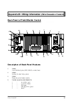

Appendix B
—
Wiring Information (Older Generation Controls)
MCP-25/MS
Valco Cincinnati
B-3
13
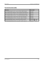
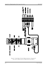
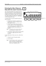
Marking valve
1
=
Coil voltage (24V)
2
=
Coil voltage (24V)
3
=
Purge button input
4
=
Purge button input
5
=
Earth
6
=
Shield
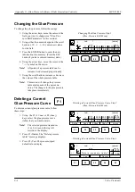
14
Scanner for marking valve
1
=
24 volt (US=red)
2
=
0 volt (US=black)
3
=
PNP signal
4
=
NPN signal (US=green)
5
=
Shield
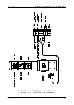
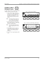
15
Bypass valve connections (maximum of 2)
1
=
Coil voltage (24V)
2
=
Coil voltage (24V)
3
=
Purge button input
4
=
Purge button input
5
=
Earth
6
=
Shield
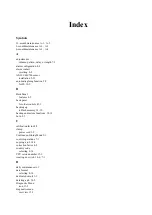
16
Scanner 6 or level indicator
1
=
+24V
2
=
0V
3
=
PNP
4
=
NPN
5
=
Shield
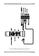
17
Pressure transducer connections (maximum of 2)
1
=
24 volt
2
=
0 volt
3
=
(-) Signal output (0-10V or 0-20mA)
4
=
(+) Signal output (0-10V or 0-20mA)
5
=
Earth
6
=
Shield
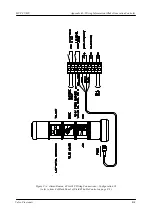
18
Fuse (F3), 24V encoder (0.5 amp-GDC)
19
Fuse (F5), 15V encoder (0.5 amp-GDC)
20
Fuse (F4), flow control (1.6 amp-GDC)
21
Fuse (F2), 24V scanner (0.5 amp-GDC)
22
Optional fiber optic interface
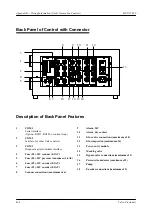
Summary of Contents for MCP-25/MS
Page 1: ...MCP 25 MS Control Manual Number MC051 Release Date June 2004 ...
Page 25: ......
Page 27: ......
Page 28: ......
Page 29: ...3 4 5 1 2 2 4 5 3 1 ...
Page 30: ......
Page 31: ......
Page 33: ...4 8 12 11 10 9 6 7 5 3 2 1 ...
Page 34: ...3 7 9 10 8 5 6 4 1 2 1 4 3 2 ...
Page 35: ...1 3 4 2 ...
Page 36: ...7 9 10 8 3 5 6 4 1 2 ...
Page 37: ...SHD NPN 5 4 3 24V Low Level Detector 0V 1 2 ...
Page 38: ......
Page 39: ......
Page 40: ......
Page 41: ......
Page 42: ......
Page 43: ...3 4 5 6 2 3 1 5 6 4 1 2 ...
Page 44: ......
Page 45: ......
Page 46: ......
Page 47: ......
Page 48: ......
Page 49: ...RODUCT 7 10 9 8 3 5 6 4 1 2 8 10 9 2 5 7 6 3 4 1 ...
Page 50: ......
Page 51: ......
Page 52: ...6 8 10 9 7 1 3 5 4 2 ...
Page 53: ......
Page 54: ......
Page 55: ...6 8 10 9 7 1 3 5 4 2 ...
Page 56: ...VA LC O CI NCIN NA TI INC 513 87 4 6550 5 13 87 4 6550 VALC O C INCIN NATI INC ...
Page 57: ......
Page 58: ......
Page 59: ......
Page 60: ......
Page 61: ......
Page 62: ......
Page 87: ......
Page 99: ...F1 F2 F3 F4 F5 ...


