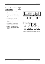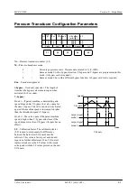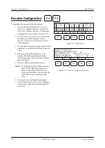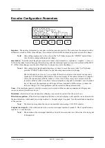
Valco Cincinnati
7-1
MC051 (July 2002)
Section 7—Operation
Introduction
This section of the manual contains job creation and adjustment procedures for MCP-25/MS control operations.
Creating a New Job
To create a new job, follow these steps:
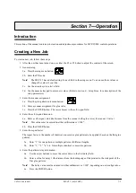
1. After the unit has been turned on, use either the F1 or F2 button to adjust the contrast of the screen.
2. General setup:
2a. Press the setup menu button.
2b. Enter the PIN code.
Note!
The MCP-25 has a default setting for each field in the setup menu. You can use these values or
change the values if you like.
2c. Use the arrow keys to select a field.
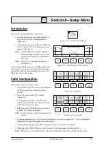
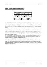
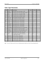
2d. Use the numeric keypad to enter new values. (Refer to
Section 8—Setup Menu
for a description of the
setup parameters.)
3. Enter the scanner assignment:
3a. Press the glue pattern edit menu button.
3b. Enter a scanner assignment for glue valve.
3c. Press the ENTER button. The cursor moves to the cell-to-gun field.
4. Enter the cell-to-gun dimension:
4a. Enter a cell-to-gun value (the distance from the scanner to the glue valve) for scanner 1/valve 1.
Note!
This value must be entered in either millimeters or 1/100".
4b. Press the ENTER button.
5. Enter the repeat factor:
The repeat factor is the number of identical, consecutive glue patterns to be applied (based on the first glue
pattern).
5a. Enter “1” for one pattern or multiple patterns of different lengths.
5b. Enter “2,” “3,” “4,” etc. for multiple, identical, consecutive patterns.
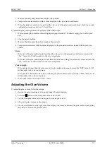
6. Enter the pattern-delay information:
6a. Use the arrow buttons to move the cursor down to the first delay field.
6b. Enter a value for delay 1 (the distance from the leading edge of the product to the start point of the
first glue pattern).
Note!
The delay value must be entered in either millimeters or 1/100", depending on unit configuration.
6c. Press the ENTER button.
Summary of Contents for MCP-25/MS
Page 1: ...MCP 25 MS Control Manual Number MC051 Release Date June 2004 ...
Page 25: ......
Page 27: ......
Page 28: ......
Page 29: ...3 4 5 1 2 2 4 5 3 1 ...
Page 30: ......
Page 31: ......
Page 33: ...4 8 12 11 10 9 6 7 5 3 2 1 ...
Page 34: ...3 7 9 10 8 5 6 4 1 2 1 4 3 2 ...
Page 35: ...1 3 4 2 ...
Page 36: ...7 9 10 8 3 5 6 4 1 2 ...
Page 37: ...SHD NPN 5 4 3 24V Low Level Detector 0V 1 2 ...
Page 38: ......
Page 39: ......
Page 40: ......
Page 41: ......
Page 42: ......
Page 43: ...3 4 5 6 2 3 1 5 6 4 1 2 ...
Page 44: ......
Page 45: ......
Page 46: ......
Page 47: ......
Page 48: ......
Page 49: ...RODUCT 7 10 9 8 3 5 6 4 1 2 8 10 9 2 5 7 6 3 4 1 ...
Page 50: ......
Page 51: ......
Page 52: ...6 8 10 9 7 1 3 5 4 2 ...
Page 53: ......
Page 54: ......
Page 55: ...6 8 10 9 7 1 3 5 4 2 ...
Page 56: ...VA LC O CI NCIN NA TI INC 513 87 4 6550 5 13 87 4 6550 VALC O C INCIN NATI INC ...
Page 57: ......
Page 58: ......
Page 59: ......
Page 60: ......
Page 61: ......
Page 62: ......
Page 87: ......
Page 99: ...F1 F2 F3 F4 F5 ...

