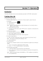
Section 8
—
Setup Menu
MCP-25/MS
Valco Cincinnati
8-8
MC051 (July 2002)
F4
Sensor and Alarm
Configuration
The optional machine-stop relay and alarm/beacon
interface are required to indicate a jam condition or
glue-inspection fault to the parent machine. To
configure the sensor and the alarm, follow these steps:
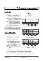
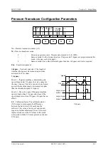
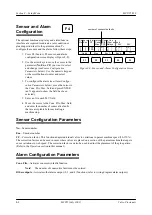
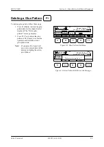
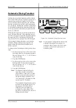
1. Press F4 (Sensor). The sensor-and-alarm
configuration screen displays (Figure 8-9).
2. Use the arrow keys to move the cursor to the
parameter (
No
,
Enc
,
CF
) you want to select
and change (see
Sensor Configuration
Parameters
below). Use the numeric keypad
or the scroll buttons to enter and select
values.
3. To configure the alarm (see
Alarm Configu-
ration Parameters
below), move the cursor to
the Cons. Flts. Max. field and press ENTER
(an X appears to show the field has been
selected).
3. Enter an X in each 24V field.
4. Move the cursor to the Cons. Flts. Max. field
and enter the number of consecutive faults
that are acceptable before activating a
machine stop.
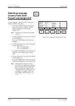
Figure 8-9. Sensor-and-Alarm Configuration Screen
Sensor and alarm confi gur ati on
1
2
1
1
1 [ X]
1 [ ]
CF
No Enc
Cons. Flts
Max. 010
Other outputs
Relays 24V 24V
F1
F2
F3
F4
F5
Valve
Pres.
Enc 1.
Enc 2.
>>>
100
100
2[ ]
3[ X]
4[ X]
2[ ]
3[ ]
4[ ]
Sensor Configuration Parameters
No
—Sensor number
Enc
—Encoder number
CF
—Correction factor. This function adapts individual valves to variations in parent machine speed (50-150%).
The correction factor can be used in cases where valves are placed on a section of the parent machine that experi-
ences variations in web speed. The correction factor can also be used to adjust the placement of the glue pattern.
(Refer to the
Operation
section in this manual.)
Alarm Configuration Parameters
Cons. Flts
—Activates consecutive faults function
Note!
The number of consecutive faults must be entered
Other outputs
—Activates other alarm output (2, 3, and 4) functions (refer to wiring diagram alarm outputs).
number of consecutive faults
Summary of Contents for MCP-25/MS
Page 1: ...MCP 25 MS Control Manual Number MC051 Release Date June 2004 ...
Page 25: ......
Page 27: ......
Page 28: ......
Page 29: ...3 4 5 1 2 2 4 5 3 1 ...
Page 30: ......
Page 31: ......
Page 33: ...4 8 12 11 10 9 6 7 5 3 2 1 ...
Page 34: ...3 7 9 10 8 5 6 4 1 2 1 4 3 2 ...
Page 35: ...1 3 4 2 ...
Page 36: ...7 9 10 8 3 5 6 4 1 2 ...
Page 37: ...SHD NPN 5 4 3 24V Low Level Detector 0V 1 2 ...
Page 38: ......
Page 39: ......
Page 40: ......
Page 41: ......
Page 42: ......
Page 43: ...3 4 5 6 2 3 1 5 6 4 1 2 ...
Page 44: ......
Page 45: ......
Page 46: ......
Page 47: ......
Page 48: ......
Page 49: ...RODUCT 7 10 9 8 3 5 6 4 1 2 8 10 9 2 5 7 6 3 4 1 ...
Page 50: ......
Page 51: ......
Page 52: ...6 8 10 9 7 1 3 5 4 2 ...
Page 53: ......
Page 54: ......
Page 55: ...6 8 10 9 7 1 3 5 4 2 ...
Page 56: ...VA LC O CI NCIN NA TI INC 513 87 4 6550 5 13 87 4 6550 VALC O C INCIN NATI INC ...
Page 57: ......
Page 58: ......
Page 59: ......
Page 60: ......
Page 61: ......
Page 62: ......
Page 87: ......
Page 99: ...F1 F2 F3 F4 F5 ...

