Section 8
—
Setup Menu
MCP-25/MS
Valco Cincinnati
8-11
MC051 (July 2002)
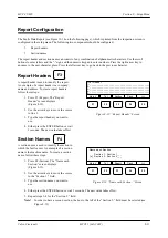
Report Headers
A report header is used to identify the report.
An example of a report header is a company
name and address. To create report headers,
follow these steps:
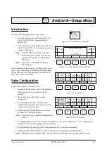
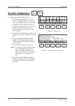
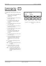
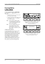
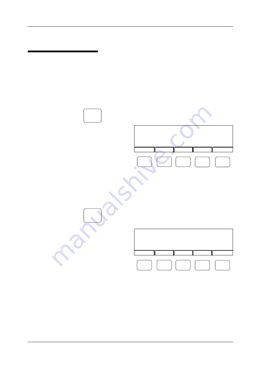
1. Press F3 (Report). The “Report
Header” screen displays
(Figure 8-12).
2. Use the arrow keys to move the cursor
to line 1.
3. Type the report header you want to
use.
4. Either press the ENTER button or wait
3 seconds. The new value takes effect.
Section Names
A section name is used to identify the section in
which the fault occurs. An example of a section
name is the machine name. To create a section
name, follow these steps:
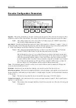
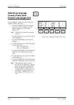
1. Press F4 (Section). The “Name each
Section:” screen displays
(Figure 8-13).
2. Use the arrow keys to move the cursor
to the “Section 1:” field.
3. Type the section name you want to
use.
F3
F4
Figure 8-12. ”Report Header” Screen
Mark.V
Tol
Section
Clock
Print Header
1 - ____________________________________________
2 - ____________________________________________
3 - ____________________________________________
4 - ____________________________________________
5 - ____________________________________________
>>>
F1
F2
F3
F4
F5
Figure 8-13. ”Name each Section:” Screen
Mark.V
Tol
Report
Clock
Name each Section:
Section 1: Section 1___
[x] Section 2: Section 2___
>>>
F1
F2
F3
F4
F5
Report Configuration
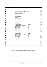
The Faults Data Report (see Figure 12-14 on the following page), which is printed from the inspection screen, is
configured in the setup menu. The following two components should be configured:
•
Report headers
•
Section names
The report header and section name can consist of any combination of alphanumeric characters. Use the scroll
buttons to enter letters and the “-” sign and the numeric keypad to enter numbers. Press the right arrow key to
advance to the next character place. Press the left arrow key to go back to the previous character.
4. Either press the ENTER button or wait 3 seconds. The new value takes effect.
5. Repeat steps 2-4 for the “Section 2:” field.
Note!
In order to have a second section, the box to the left of the “Section 2:” field must be selected (see
Figure 8-13).
Summary of Contents for MCP-25/MS
Page 1: ...MCP 25 MS Control Manual Number MC051 Release Date June 2004 ...
Page 25: ......
Page 27: ......
Page 28: ......
Page 29: ...3 4 5 1 2 2 4 5 3 1 ...
Page 30: ......
Page 31: ......
Page 33: ...4 8 12 11 10 9 6 7 5 3 2 1 ...
Page 34: ...3 7 9 10 8 5 6 4 1 2 1 4 3 2 ...
Page 35: ...1 3 4 2 ...
Page 36: ...7 9 10 8 3 5 6 4 1 2 ...
Page 37: ...SHD NPN 5 4 3 24V Low Level Detector 0V 1 2 ...
Page 38: ......
Page 39: ......
Page 40: ......
Page 41: ......
Page 42: ......
Page 43: ...3 4 5 6 2 3 1 5 6 4 1 2 ...
Page 44: ......
Page 45: ......
Page 46: ......
Page 47: ......
Page 48: ......
Page 49: ...RODUCT 7 10 9 8 3 5 6 4 1 2 8 10 9 2 5 7 6 3 4 1 ...
Page 50: ......
Page 51: ......
Page 52: ...6 8 10 9 7 1 3 5 4 2 ...
Page 53: ......
Page 54: ......
Page 55: ...6 8 10 9 7 1 3 5 4 2 ...
Page 56: ...VA LC O CI NCIN NA TI INC 513 87 4 6550 5 13 87 4 6550 VALC O C INCIN NATI INC ...
Page 57: ......
Page 58: ......
Page 59: ......
Page 60: ......
Page 61: ......
Page 62: ......
Page 87: ......
Page 99: ...F1 F2 F3 F4 F5 ...

