Valco Cincinnati
9-1
MC051 (July 2002)
Introduction
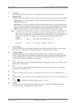
The glue-pattern-edit menu allows you to edit glue
patterns. To access the glue-pattern-edit menu,
follow this step:
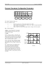
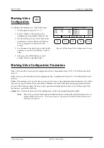
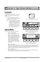
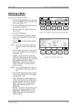
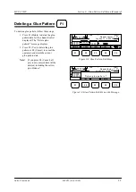
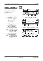
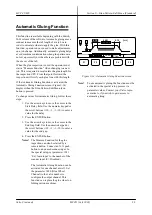
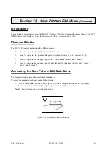
1. Press the glue-pattern-edit icon button
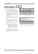
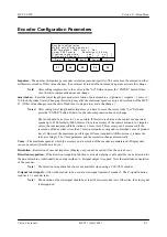
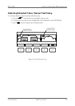
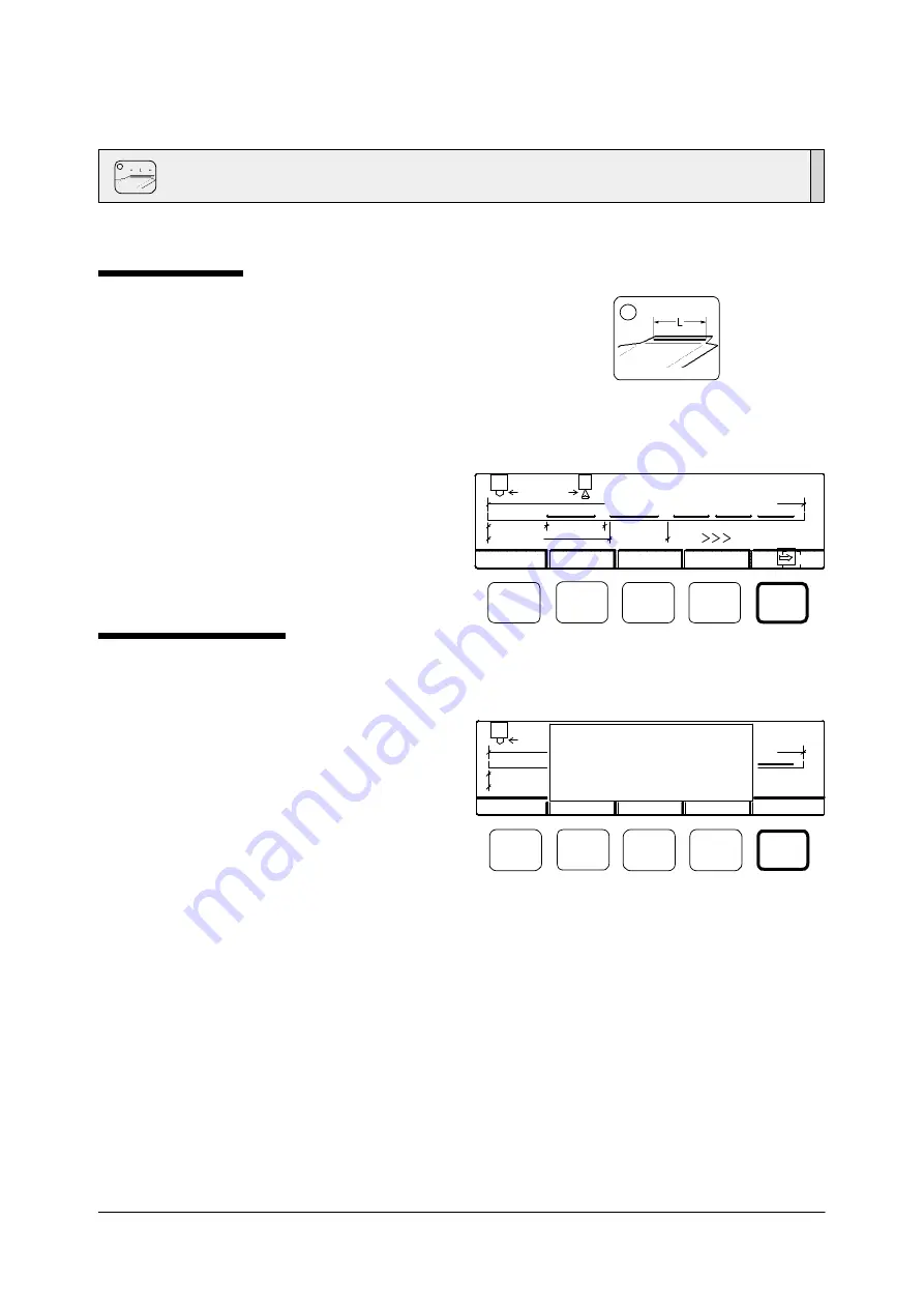
(Figure 9-1). The glue-pattern-edit menu
displays (Figures 9-2 and 9-3).
Note!
One of four glue-pattern-edit menus
displays, depending on which mode
(standard, continuous-gluing, stitch,
or jogging) is currently selected in the
mode-selection screen. To select a
different mode, see
Selecting a Mode
later in this section. Each valve can
run in an independent mode.
Types of Modes
There are four types of gluing operation modes:
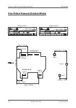
•
Mode 0—Standard Mode
Contains programmable glue patterns.
•
Mode 1—Continuous-Gluing Mode
Gluing is activated or deactivated using
the Vmin minimum-speed setting. This
mode is Vmin dependent—the valve
turns on when the parent machine
operates above the minimum-speed
setting, and turns off when the parent
machine operates below the minimum-
speed setting.
Section 9—Glue-Pattern-Edit Menu
(Standard)
•
Mode 2—Stitch Mode
Stitch mode is used for discontinuous lines. This mode is useful for economical application of long lines
of glue. It allows different input possibility of bead length and gap length. Intermittent gluing is also
possible. The control will take into account that each pattern ends with applied glue (not with a gap). Be
aware that it can cause the gap to deviate slightly from the entered value.
•
Mode 3—Jogging Mode
Jogging mode is used for extremely low speeds. Jog-speed gluing is activated or deactivated by using
the V-jogging speed setting (possible inputs of dot size and gap length).
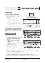
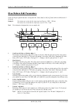
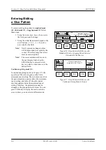
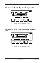
Figure 9-2. Glue-Pattern-Edit Menu with
Standard, Stitch, or Jogging Mode Selected
(Standard Mode Shown)
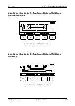
Figure 9-3. Glue-Pattern-Edit Menu with
Continuous-Gluing Mode Selected
MODE 1
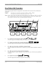
Figure 9-1. Glue-Pattern-Edit Icon Button
Repeat factor = 01
1
1
00000
00000
00000
00000
00000
Job:
1
[mm]
Lockout = 0 00000
MODE 0
F1
F2
F3
F4
F5
Delete
Copy
+ Chan.
^
Chan.
^-
tor = 01
Valve oper ati on
depends on Vmi n ! !
Forward
Back
1
0 0
00000
00000
[mm]
00
Mode
F1
F2
F3
F4
F5
Summary of Contents for MCP-25/MS
Page 1: ...MCP 25 MS Control Manual Number MC051 Release Date June 2004 ...
Page 25: ......
Page 27: ......
Page 28: ......
Page 29: ...3 4 5 1 2 2 4 5 3 1 ...
Page 30: ......
Page 31: ......
Page 33: ...4 8 12 11 10 9 6 7 5 3 2 1 ...
Page 34: ...3 7 9 10 8 5 6 4 1 2 1 4 3 2 ...
Page 35: ...1 3 4 2 ...
Page 36: ...7 9 10 8 3 5 6 4 1 2 ...
Page 37: ...SHD NPN 5 4 3 24V Low Level Detector 0V 1 2 ...
Page 38: ......
Page 39: ......
Page 40: ......
Page 41: ......
Page 42: ......
Page 43: ...3 4 5 6 2 3 1 5 6 4 1 2 ...
Page 44: ......
Page 45: ......
Page 46: ......
Page 47: ......
Page 48: ......
Page 49: ...RODUCT 7 10 9 8 3 5 6 4 1 2 8 10 9 2 5 7 6 3 4 1 ...
Page 50: ......
Page 51: ......
Page 52: ...6 8 10 9 7 1 3 5 4 2 ...
Page 53: ......
Page 54: ......
Page 55: ...6 8 10 9 7 1 3 5 4 2 ...
Page 56: ...VA LC O CI NCIN NA TI INC 513 87 4 6550 5 13 87 4 6550 VALC O C INCIN NATI INC ...
Page 57: ......
Page 58: ......
Page 59: ......
Page 60: ......
Page 61: ......
Page 62: ......
Page 87: ......
Page 99: ...F1 F2 F3 F4 F5 ...

