Section 9
—
Glue-Pattern-Edit Menu (Standard)
MCP-25/MS
Valco Cincinnati
9-3
MC051 (July 2002)
7
Job Name
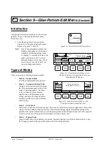
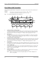
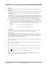
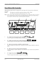
This field displays the name of the job. The job name cannot be edited in the glue-pattern-edit screen.
8
Repeat Factor
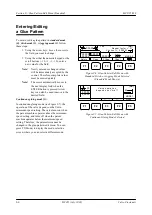
This field contains the number of identical, consecutive glue patterns (based on the first pattern specified).
If repeat factor = 1
, the glue pattern (as entered) will be applied one time (there are a maximum of 5
independent glue lines).
If repeat factor = 2 to 99
, the complete glue pattern will be applied by the valve (maximum of 4 glue
lines) 2 to 99 times. The pattern startpoint (delay) of the repetition is the last startpoint given in the glue-
pattern-edit menu. Therefore, it is important that the corresponding glue pattern length is set to 0. The
difference between the first startpoint and the last is the distance between the pattern repetitions.
Note!
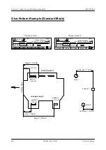
The repeat factor function will not work unless a startpoint (delay) is entered for the pattern that will
follow the entered pattern. (See “Glue-Pattern Example (Standard Mode)” later in this section.) For
this reason, up to four identical or non-identical patterns can be used by each valve (maximum of 5 in
the case of no repetition). The startpoint of the repetition is the delay after the last glue line.
Example:
2 glue lines:
delay 3
^
start of repeat, glue length 3 must be “0”
=
4 glue lines:
delay 5
^
start of repeat, glue length 5 must be “0”
=
9
Unit of Measure
This field indicates the unit of measure (millimeters or inches) that has been selected in the setup menu.
(See
Section 11—Setup Menu
for information about how to change the unit of measure.)
10
Scanner Lockout
This field contains the lockout length of the scanner signal. The scanner signal is not accepted once a
lockout length has been entered. This function can be used to bypass cutouts on the product. The entered
lockout length should be 10 mm (0010) or 1/2 inch (00.50) longer than the product cutout. Maximum
allowable lockout length is 19999mm or 199.99 inches.
11
F1
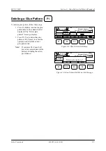
Press F1 (DELETE) to delete the glue-pattern information for this channel (valve). (See “Deleting a Glue
Pattern” later in this section.)
12
F2
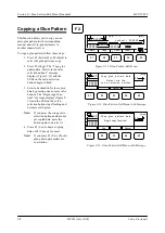
Press F2 (COPY) to copy the glue pattern information for this valve to another valve. (See “Copying a
Glue Pattern” later in this section.)
13
F3
^
Press F3 (
+
Chan.) to display the edit screen for the next valve. Up to 8 valves are available in 1 job.
14
F4
_
Pressing F4 (Chan.
v
) to display the edit screen of the previous valve. Up to 8 valves are available in 1 job.
15
F5
Press F5 ( ) to display the information for glue patterns 3, 4, and 5.
16
MODE
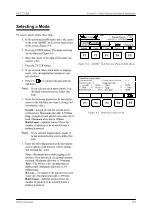
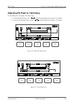
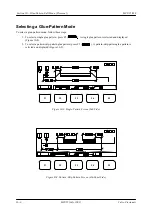
Moving the cursor to the word “MODE” and then pressing the “ENTER” button displays the mode-
selection screen (see “Selecting a Mode” in this section”).
Summary of Contents for MCP-25/MS
Page 1: ...MCP 25 MS Control Manual Number MC051 Release Date June 2004 ...
Page 25: ......
Page 27: ......
Page 28: ......
Page 29: ...3 4 5 1 2 2 4 5 3 1 ...
Page 30: ......
Page 31: ......
Page 33: ...4 8 12 11 10 9 6 7 5 3 2 1 ...
Page 34: ...3 7 9 10 8 5 6 4 1 2 1 4 3 2 ...
Page 35: ...1 3 4 2 ...
Page 36: ...7 9 10 8 3 5 6 4 1 2 ...
Page 37: ...SHD NPN 5 4 3 24V Low Level Detector 0V 1 2 ...
Page 38: ......
Page 39: ......
Page 40: ......
Page 41: ......
Page 42: ......
Page 43: ...3 4 5 6 2 3 1 5 6 4 1 2 ...
Page 44: ......
Page 45: ......
Page 46: ......
Page 47: ......
Page 48: ......
Page 49: ...RODUCT 7 10 9 8 3 5 6 4 1 2 8 10 9 2 5 7 6 3 4 1 ...
Page 50: ......
Page 51: ......
Page 52: ...6 8 10 9 7 1 3 5 4 2 ...
Page 53: ......
Page 54: ......
Page 55: ...6 8 10 9 7 1 3 5 4 2 ...
Page 56: ...VA LC O CI NCIN NA TI INC 513 87 4 6550 5 13 87 4 6550 VALC O C INCIN NATI INC ...
Page 57: ......
Page 58: ......
Page 59: ......
Page 60: ......
Page 61: ......
Page 62: ......
Page 87: ......
Page 99: ...F1 F2 F3 F4 F5 ...

