


Digital Input / Output Protocol
Digital input/output control of the multiposition actuator is designed for simplicity and flexibility of
function. The simplest control of the actuator can be accomplished with two output control lines –
STEP and HOME. On the other hand, the actuator can accept a latched BCD input with manual and
automatic direction signals.
The inputs are held to a logical high (+5 volts) by pull-up resistors, and are designed to be driven low
either by contact closure, 5 volt digital logic, or open collector transistor outputs. The signal polarity is
defined as “negative true” – asserting the signal involves shorting the signal (in the case of contact
closure) or driving it (in the case of logic or transistor signals) to within 0.8 volts of ground potential.
These input signals must be at least 30 milliseconds in duration. The outputs are also “negative true”
signals driven by standard high speed CMOS gates, capable of driving standard logic input gates.
They include the BCD position, motor run, rotational direction, and error signals. If the actuator stops
out of position due to a stuck valve, the BCD output is set to “0” (all lines high for a negative true
output).
The digital interface is made through a 26 pin connector which also provides power (+5 volts/100 ma
maximum) and ground outputs. The ground should be connected to the control system to maintain
commonality between the actuator and the controlling device. If you intend to provide your own
power supply, make sure that it has an isolated output or that it shares a common ground with the
controlling system.
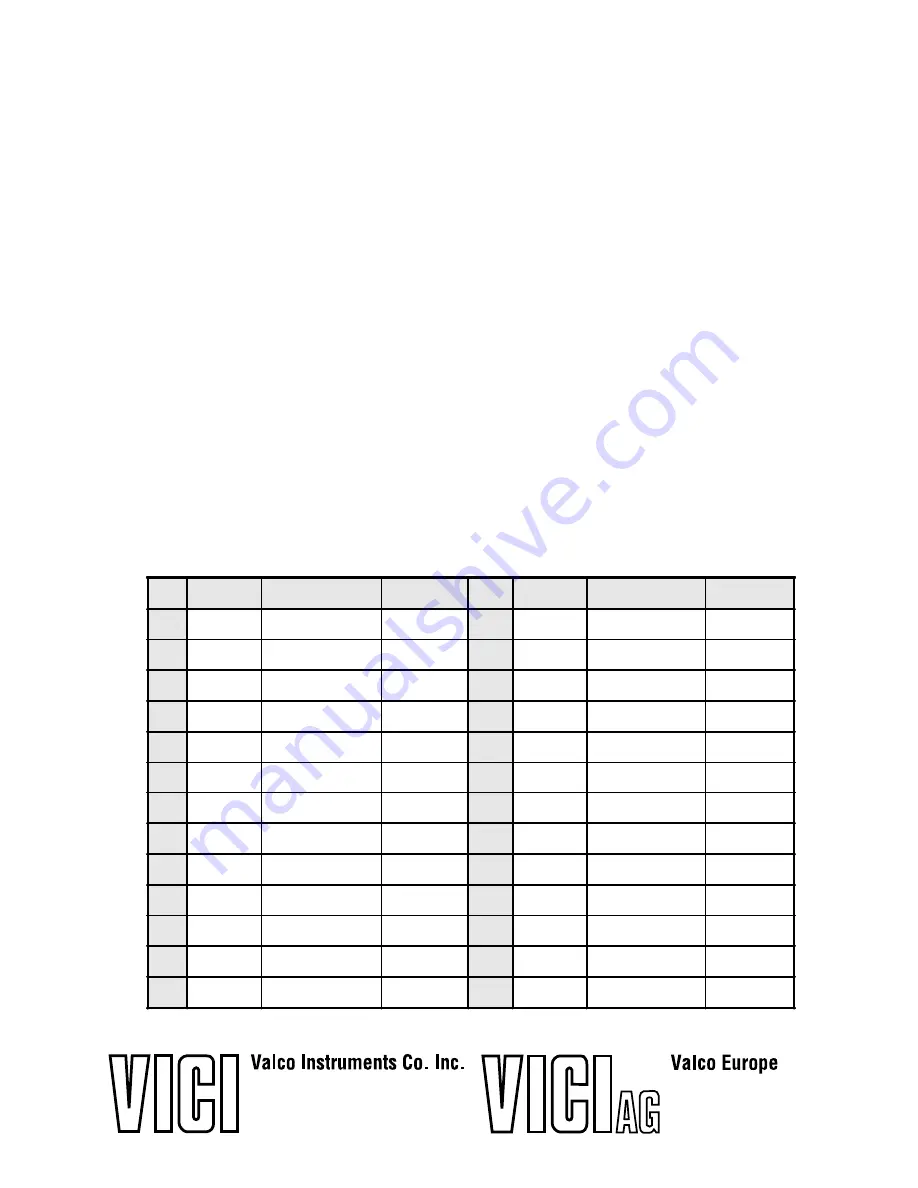
Pin signal definitions for the Digital Input/Output cable
Pin
Color
Signal
Direction
Pin
Color
Signal
Direction
1
brown
Home
Input
14
yellow
1.4 BCD
Output
2
red
Motor run
Output
15
green
10.2 BCD
Output
3
orange
Step
Input
16
blue
1.2 BCD
Output
4
yellow
Error
Output
17
violet
10.1 BCD
Output
5
green
Manual Dir.
Input
18
gray
1.1 BCD
Output
6
blue
Direction
Output
19
white
10.8 BCD
Input
7
violet
Auto Dir.
Input
20
black
1.8 BCD
Input
8
gray
Data latch
Input
21
brown
10.4 BCD
Input
9
white
+5 VDC 100 ma
Output
22
red
1.4 BCD
Input
10
black
Ground
Output
23
orange
10.2 BCD
Input
11
brown
10.8 BCD
Output
24
yellow
1.2 BCD
Input
12
red
1.8 BCD
Output
25
green
10.1 BCD
Input
13
orange
10.4 BCD
Output
26
blue
1.1 BCD
Input
Untertannberg 7
CH-6214 Schenkon
Switzerland
Telephone (041) 925-6200
Fax (041) 925-6201
P. O. Box 55603
Houston, TX 77255
Sales toll-free (800) FOR VICI
Technical help (713) 688-9345
Fax (713) 688-8106


