background image

AS-1735/SRC

VTM-01-003C

Valcom Mfg Grp, Inc.

-6-

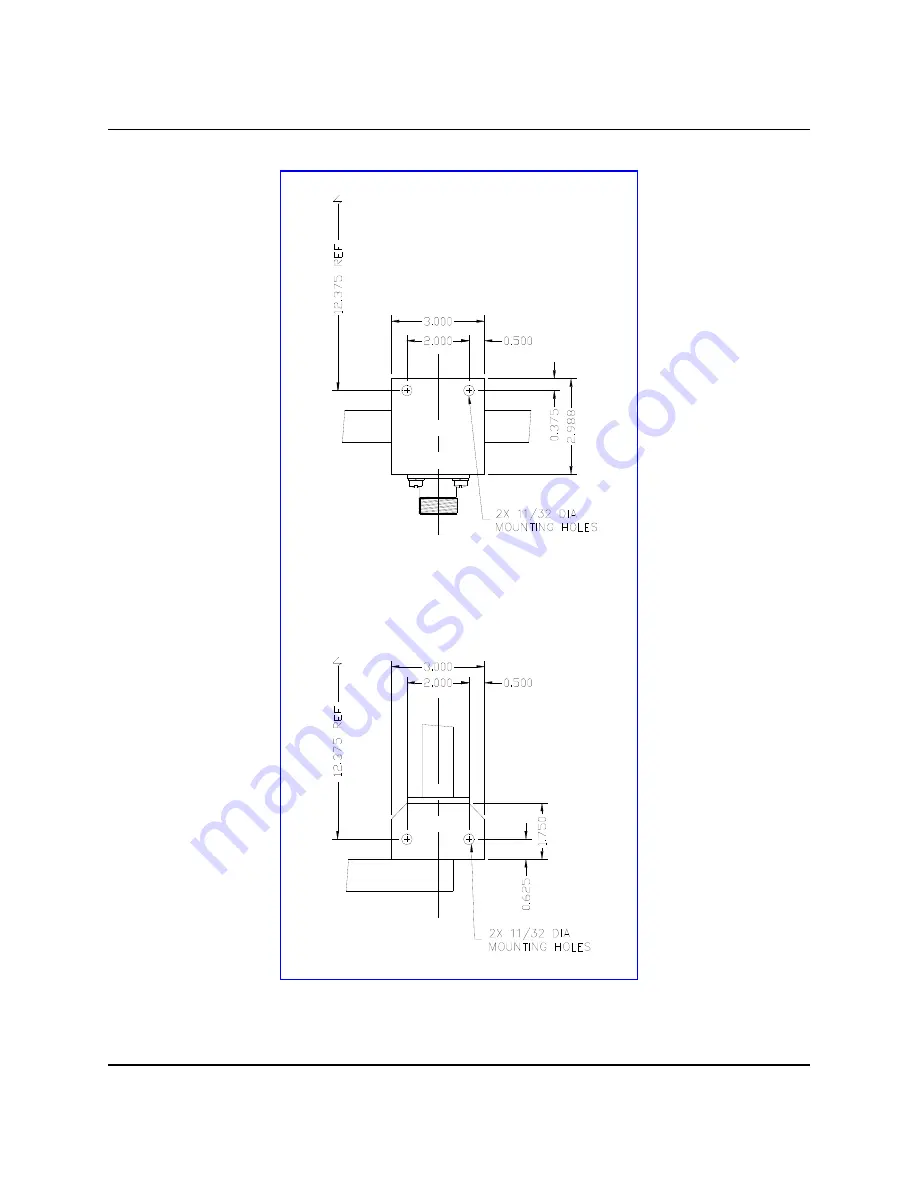
Figure 2.3.a

 -  Lower mounting hole dimensions

of the AS-1735/SRC antenna

Summary of Contents for AS-1735/SRC

Page 1: ...ate Drive P O Box 603 Guelph Ontario Canada N1H 6L3 Tel 519 824 3220 Fax 519 824 3411 Web Site www valcommfg ca E mail enquiries valcom guelph com TECHNICAL MANUAL VTM 01 003 Rev C OPERATION AND INSTA...

Page 2: ......

Page 3: ...ion Description Date A Original Issue July 20 2001 B Various formatting changes to improve readability May 28 2002 C Updated contact information October 7 2013 Errors in this publication can be report...

Page 4: ......

Page 5: ...ing 4 2 5 Site Preparations 4 2 6 Installation Requirements 4 2 7 Alternate Installation Method 8 3 0 OPERATION 10 3 1 Functional Description 10 3 2 Operating Procedures 10 4 0 TROUBLE SHOOTING AND MA...

Page 6: ...1 Parts supplied with AS 1735 SRC antenna Shipment 12 Table 5 2 Optional Parts available for the AS 1735 SRC antenna 12 FIGURES Figure 2 1 Identifying the main sections of the AS 1735 SRC 3 Figure 2 2...

Page 7: ...from the manufacturer See Section 6 for contact information The AS 1735 SRC antenna is comprised of a four element array with each element equally spaced around a central mountable mast The broadband...

Page 8: ...5 cm dia Optional 12 to 15 inch 30 5 to 38 1 cm dia Overall Dimensions 29 3 4 in wide x 29 3 4 in deep x 28 1 4 in high 75 6 cm wide x 75 6 cm deep x 71 8 cm high Temperature Storage 140 F to 158 F 9...

Page 9: ...er Carefully pry off the lid of the shipping container to find the antenna and the two manuals in amongst the packing material See Figure 2 1 Lift out the top layer of packing material and carefully r...

Page 10: ...st to prevent excessive stress on the connector assemblies of both the transmission line itself and the antenna 2 5 Site Preparations The AS 1735 SRC antenna has been designed for shipboard use and is...

Page 11: ...r Feed Section and the Left hand and Right hand Radiating Element Sections see Figure 2 1 The Lower Section is equipped with three mounting flanges Each flange has 2 bolt holes to accommodate 3 8 hard...

Page 12: ...AS 1735 SRC VTM 01 003C Valcom Mfg Grp Inc 6 Figure 2 3 a Lower mounting hole dimensions of the AS 1735 SRC antenna...

Page 13: ...AS 1735 SRC VTM 01 003C Valcom Mfg Grp Inc 7 Figure 2 3 b Upper mounting hole dimensions of the AS 1735 SRC antenna...

Page 14: ...not critical as the antenna is designed to provide omnidirectional radiation in the azimuth plane The easiest recommended installation is to raise the antenna to the top of the mast then sliding it do...

Page 15: ...inner conductor bullet connections attach the Lower Feed Section to the two Radiating Element Sections Use the stainless steel hardware previously removed to secure the three sections together Tighten...

Page 16: ...allelling those with the other two elements which are also in parallel to each other The radiation pattern of the antenna is essentially that of a vertically polarized dipole When the antenna is mount...

Page 17: ...d 4 3 Typical Troubles The main area of concern would be the UG 352 connector check for solid contact on the threads and that the centre contact is not broken or loose Symptoms of a poor connector wou...

Page 18: ...e from the manufacturer appears in Table 5 2 Table 5 1 Parts supplied with AS 1735 SRC antenna Shipment Item Part Number Description Quantity 1 VD 00 00171 1 AS 1735 SRC Antenna 1 2 VTM 01 003 Technic...

Page 19: ...2 Manufacturer s Address Postal address Shipping address Valcom Manufacturing Group Inc P O Box 603 Guelph Ontario Canada N1H 6L3 Valcom Manufcaturing Group Inc 175 Southgate Drive Hanlon Industrial...

Reviews: