


6 947100
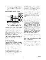
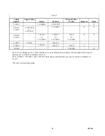
Station Level
Page Adapter
Page
Control /
Interface
Incoming C. O.
or Centrex line or
a PABX Station
or
DIAGRAM 3
Block Diagram of Connections to a Valcom
Page Control/Interface
Your Telephone or
Telephone System
SYSTEM INSTALLATION
General
These instructions will provide a basic understanding
for wiring Valcom one-way paging equipment and
connecting it to a telephone system.
For specific wiring information, consult the installation
practice enclosed with the actual equipment being
used.
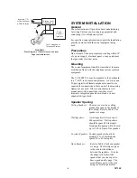
Precautions
Do not locate Valcom equipment or cabling within 18"
of a power supply, electrical panel, or any equipment
that generates electrical noise.
Mounting
The control equipment should be installed at the main
distribution frame with the telephone system common
equipment.
The V-1109RTVA, may be mounted to the backboard,
in a 7" KTU rack or mounting frames. A 66-type and
25-pair pigtail with female amphenol connector are
required for connections to these units if the mounting
frames are not used. Other control units are wall
mount units with connections via either screw
terminals, integrated punch down block, or a user
supplied 66-type block.
Speaker Spacing
Ceiling Speakers:
The area covered by a ceiling
speaker depends on the height of
the ceiling. Refer to Table 5 for
speaker coverage.
Wall Speakers:
A wall speaker will cover up to
600 square feet. Wall speakers
should be spaced 20 feet apart.
Good quality paging will be heard
up to 30 ft. in front of the speaker.
Corridor Speakers:
Corridor speakers should be
mounted 8 to 12 feet high and
spaced 30 to 40 feet apart.
Horn Speakers:
Refer to Table 6 for horn speaker
coverage. The first figure given
is the side to side distance
between the speakers. It is also
the distance in front of the
speaker that you can expect to
hear a good quality page. The
second figure given is the area
being covered in square feet.


