3
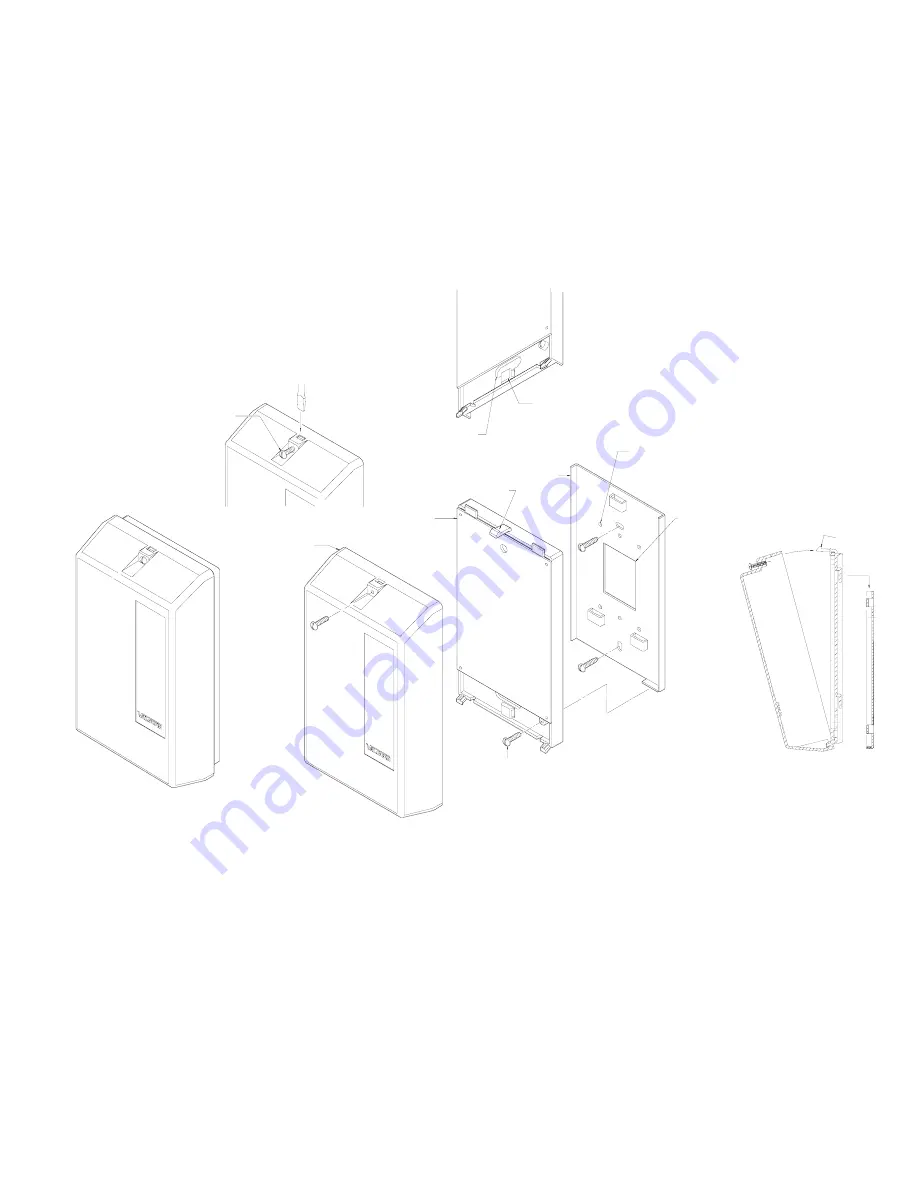
TO REMOVE COVER
LOOSEN SCREW,
THEN ACTIVATE LATCH
PLASTIC
COVER
CIRCUIT BOARD
HOUSING ASSEMBLY
SNAP LATCH
METAL WALL
MOUNTING
PLATE
WIREWAY OPENING
TO WALL PLATE AND
JUNCTION BOX
WIRE TIE LOOP
WIRE TIE USED TO BUNDLE WIRES
ENTERING AND LEAVING TERMINAL AREA
SNAP LATCH
FOR COVER
.155 DIA. HOLES FOR MOUNTING TO
SINGLE OR DOUBLE GANG JUNCTION BOX
HOLE PATTERN MATCHES BOTH EURO
AND US JUNCTION BOXES
1.5 x 2 WIRE ACCESS OPENING
TO JUNCTION BOX
BRACKET
LOCKING
SCREW
Mounting
Remove the metal mounting plate from the rear of the V-9937 enclosure. Using two #6 ¾ inch wood screws,
mount the plate in a vacant space on the backboard with the telephone system common equipment.
Both
mounting holes must be utilized to insure secure mounting of the unit
.
Provisions for mounting to a
single or double gang junction box are provided. See Figure 2
Open the V-9937 enclosure to allow access to connections and option switches. Slide the rear of the unit
(contains the board) onto the mounting plate. Lock enclosure to mounting plate with screw provided. Make
connections. Replace cover and lock in place with #6 ½ inch screws provided.
FIGURE 2
MOUNTING
EXPLODED VIEW


