4
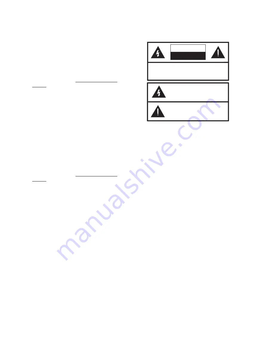
CAUTION: To reduce the risk of electric shock,
Do not remove cover.
No user serviceable parts inside.
Refer servicing to qualified service personnel.
This symbol indicates that dangerous
voltage constituting a risk of electric
shock is present within this unit.
This symbol indicates that there are
important operating and maintenance
instructions in the literature accompanying
this unit.
CAUTION
RISK OF ELECTRIC SHOCK
DO NOT OPEN
timeout, turn one of dip switches 2 through 7
"ON"
.
Refer to Figure 4 for the maximum
page length each dip switch allows.
Time Out Release
The V-9940 will release from the line a
pre-determined amount of time after ring trip as
determined by dip switch settings.
Typical Applications: Access from a PABX
Station to one zone of talkback page (station
level access not normally used with talkback).
Dip Switch Settings: Set dip switches 1 and 8
"ON". Set one of dip switches 2 through 7 "ON"
to select the maximum page length.
NOTE: This setting assigns a limited page
length. See PABX Station level Paging to
determine if the PABX is compatible for
station level page.
Audio Sense Release
The V-9940 will release from the line after a
pre-determined amount of time that silence is
detected as determined by dip switch settings.
Typical Applications: Access from a PABX
Station to one zone of one-way page or multiple
zones of one-way page using multiple PABX
stations and multiple V-9940s.
Dip switch settings: Set dip switch 1 "OFF", dip
switch 8 "ON". Set one of dip switches 2
through 7 "ON" to select the length of time the
unit stays active after last sensing audio.
(Normally dip switch 6 or 7 - for 8 or 4 seconds).
NOTE:
This setting provides unlimited page
length. See PABX Station Level Paging to
determine if the PABX is compatible for
station level page. When used with talkback
paging, the talkback audio may delay or
cancel the audio sense release.
In some special applications, a manual reset
can be used to provide release from the line by
providing a momentary ground to the manual
reset pin of the V-9940.
INSTALLATION
Regulatory Information
This equipment is to be installed only in
restricted access areas (dedicated equipment
rooms, equipment closets or the like) in
accordance with Articles 110-16, 110-17, and
110-18 of the National Electrical Code,
ANSI/NFPA No. 70.
.
When using this equipment, basic safety
precautions should always be followed to reduce
the risk of fire, electric shock and injury to
persons including the following:
1. Never install telephone wiring during a
lightning storm.
2. Never install telephone jacks in wet
locations unless the jack is specifically
designed for wet locations.
3. Never touch uninsulated telephone wires or
terminals unless the telephone line has
been disconnected at the network interface.
4. Use caution when installing or modifying
telephone lines.
General
The following sections contain step-by-step
instructions for wiring the V-9940 and
associated Valcom equipment. If the results of a
test do not correspond with what is shown, DO
NOT PROCEED UNTIL THE PROBLEM HAS
BEEN CORRECTED.
During installation, Figure 2 may be referred to
for location and numbering of punchdown block.
Refer to Figure 3 for punchdown block pinouts
and Figure 4 for dip switch settings.
NOTE: To aid system testing and balancing,
be sure to set the individual volume controls
at approximately ½ volume when installing
one-way amplified speaker assemblies.
Mounting
Remove the metal mounting plate from the rear
of the V-9940 enclosure. Using two #6 ¾ inch
wood screws, mount the plate in a vacant space
on the backboard with the telephone system
common equipment.
Both mounting holes
must be utilized to insure secure mounting


