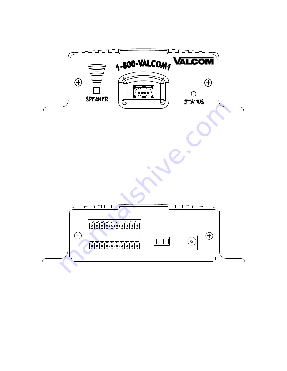
Multi-Messager USB Layout Summary
:
Front of Unit
SPEAKER - The SPEAKER switch can be turned ON and OFF to monitor audio. The switch has no effect on the
audio output connections on the rear of the unit. Switch should normally be kept OFF.
USB PLUG - The USB drive is inserted here to play audio. If insertion of drive is difficult, turn the drive over and
try reinserting. Drive should slide into jack smoothly.
STATUS - The STATUS indicator is a LED that during normal operation with a USB drive inserted into the unit
will be SOLID BLUE. If there is a problem with the drive, it is not inserted or it is empty, the LED will BLINK
BLUE.
Rear of Unit
I/O BLOCK - This 20-pin modular header accepts two 10-pin screw-down socket blocks that are included in the
accessory pack. For further instructions turn to page 6.
POWER - Use this switch to turn the unit ON and OFF.
12VDC - This is where the supplied 12VDC @ 500mA power pack is connected.
GND
1
2
3
4
5
6
7
8
ST
OP
8Ω
600Ω
N/C
BGM
GND
ACT
+ OUT
- OUT
GND
600Ω
POWER
OFF
ON
12VDC
500mA
4
Summary of Contents for V-9989
Page 2: ......


