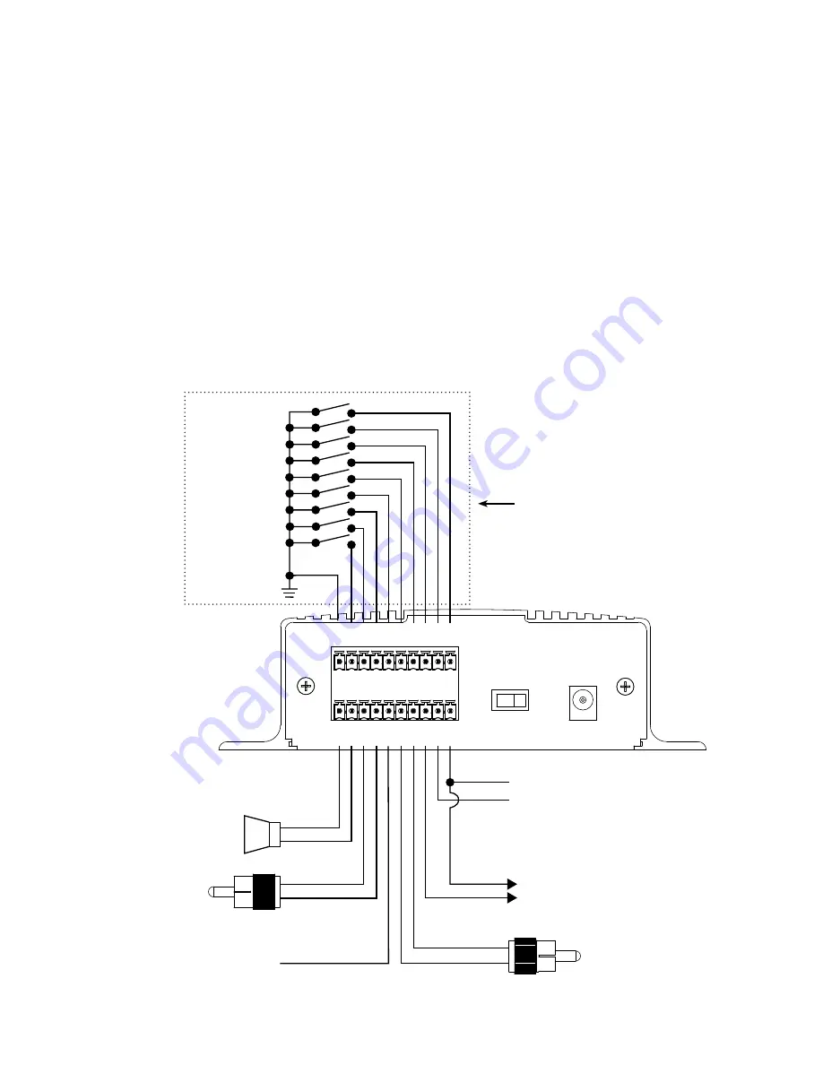
Installation:
The Multi-Messager should be installed using the following steps outlined below:
Step 1: Wire the terminal blocks that are supplied with the kit.
Use the chart below to wire the terminal blocks for the features that are applicable to your application. Two
terminal blocks, two RCA audio cords and a screwdriver have been supplied in the accessory kit.
The TRIGGER & STOP terminals should use CAT 3/5 wire.
The 8Ω, 600Ω and BGM connections should use the RCA to fly leads cable suppled in the accessory kit.
The ACTIVE TRIGGER output & 12VDC auxiliary power out should use 22 or 24 gauge wire.
The ACTIVE TRIGGER output is rated at 25mA. A relay is required if 25mA will be exceeded.
6
GND
1
2
3
4
5
6
7
8
ST
OP
8Ω
600Ω
N/C
BGM
GND
ACT
+ OUT
- OUT
GND
600Ω
POWER
OFF
ON
12VDC
500mA
STOP
MESSAGE 7
MESSAGE 6
MESSAGE 5
MESSAGE 8
8Ω
SPEAKER
+
-
600Ω LINE OUT
+
-
NO CONNECTION
+
-
-
+
12VDC AUX @ 250mA
ACTIVE
ACTIVE
+
-
MESSAGE 4
MESSAGE 3
MESSAGE 2
MESSAGE 1
GROUND
BGM LINE IN
Example NO Circuit
Summary of Contents for V-9989
Page 2: ......


