2
947564
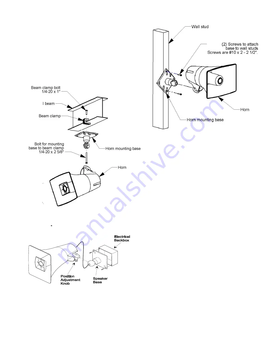
Mount the base to wall studs using the two
holes provided. Knockout holes are
provided for punch out should additional
holes be desired. See Figure 3.
The horn may be rotated or moved up and down
to obtain the desired position by loosening the
position adjustment knob at the bottom of the
unit approximately one turn. Make required
adjustments and re-tighten knob.
Figure 1. M
ounting to a Beam with a “C” Clamp
Figure 2. Mounting to an Electrical Backbox
Figure 3. Mounting to a Wall Stud
Interconnections
The only method of powering the VIP-130AL-SA
IP Paging Horn is via a Power over Ethernet
(PoE) switch or power injector meeting the
802.3af specification.
Make all required signal connections before
connecting to Ethernet switch or power injector
meeting the 802.3af specification. Power is
supplied to the horn assembly via the Network
Interface
Signal Connections
Audio output connection is made from the Signal
Output. The RJ-45 connector on the horn is
connected directly to the RJ-45 Signal Output
socket on the IP Link. If additional length is
required, any standard T568B extension may be
used. See Figure 4.
Network Connection
The Network Interface has one RJ-45 network
connector. Use a standard Ethernet patch cable
to connect the Network Interface to an Ethernet
switch.


