
3 947465
INSTALLATION
Assembly and Mounting
The VIP-429A-A is designed for recessed or flush
mounting to a Valcom backbox (not included). For
recessed mounting, the Valcom VB-R22 may be
used. For surface mounting, use the Valcom
VB-S23 or VB-A24.
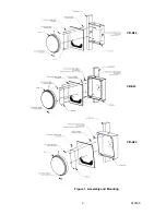
Mount the clock face to the speaker grille using the
clock mounting bracket included in the clock
package (See Figure 1). The mounting bracket
should be attached to the speaker grille using two
screws and nuts provided, with the large
rectangular cutout in the bracket aligned with the
similar hole in the grille.
Before mounting the clock to the bracket, remove
the shipping pin from the back of the clock
movement. Connect the 5-pin Molex connector to
the clock movement and route the wiring harness
through one of the square cutouts in the speaker
grille to the clock circuit board. Insert the 4-pin
screw connector into the receptacle on the clock
circuit board. Mount the clock face to the clock
bracket with the two black screws provided
With the clock mounted to the speaker grille,
connect an RJ-45 Ethernet cable to the network
jack on the speaker circuit board, then mount the
grille to the backbox with the hardware provided.
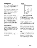
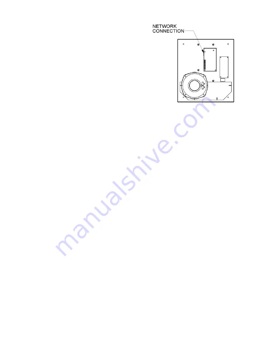
Network Connection
The VIP-429A-A has one RJ-45 network connector
on the rear panel. Use a standard patch cable to
connect the VIP-429A-A to an Ethernet switch
providing Power over Ethernet (PoE) meeting the
802.3af specification. If the switch does not provide
power, a mid-span power injector may be used.
(See Figure 2)
.
Mute Out Connection
The Mute Out may optionally be connected to the
mute input of Valcom Classroom audio
management systems in order to suspend locally
originated classroom audio during intercom
announcements.
Figure 2. Ethernet Connection
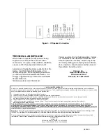
Call Switch Connection
The Talkback IP Speaker provides a call switch
input via screw terminal connections. Connect a
momentary contact switch to Switch 1 and Ground.
See Figure 3 for detailed connections.
-10 dB Line Level Out Connection
The -10dBm Line Level Out may be connected to
up to 40 Valcom Self Amplified Speakers in order to
provide additional sound reinforcement in an area.
LED Connection
LED 1 (+) and LED 2 (-) is a current limited output
designed to illuminate an optional LED. The LED is
intended to provide visual indication of call
progress. The LED illumination will flash when the
call switch is pressed and will continue to flash until
the call is answered. The LED illumination will be
solid when a connection to the unit is established.
Setup
Information specific to your application will need to
be programmed to the VIP-429A-A using a
computer. The PC used for programming should
be connected to the same subnet as VIP-429A-A.
Setup will be done using the IP Solutions Setup
Tool. Download the latest version of the free IP
Solutions Setup Tool from Valcom web site at
www.valcom.com/vipsetuptool.


