
3
947096
If external power is supplied via the barrel
connector, make all signal connections on the rear
panel and attach the unit to the network via the front
panel RJ-45 Ethernet connector. Apply power by
plugging the power supply into the VIP-MC via the
jack on the rear of the VIP-MC.
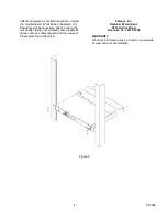
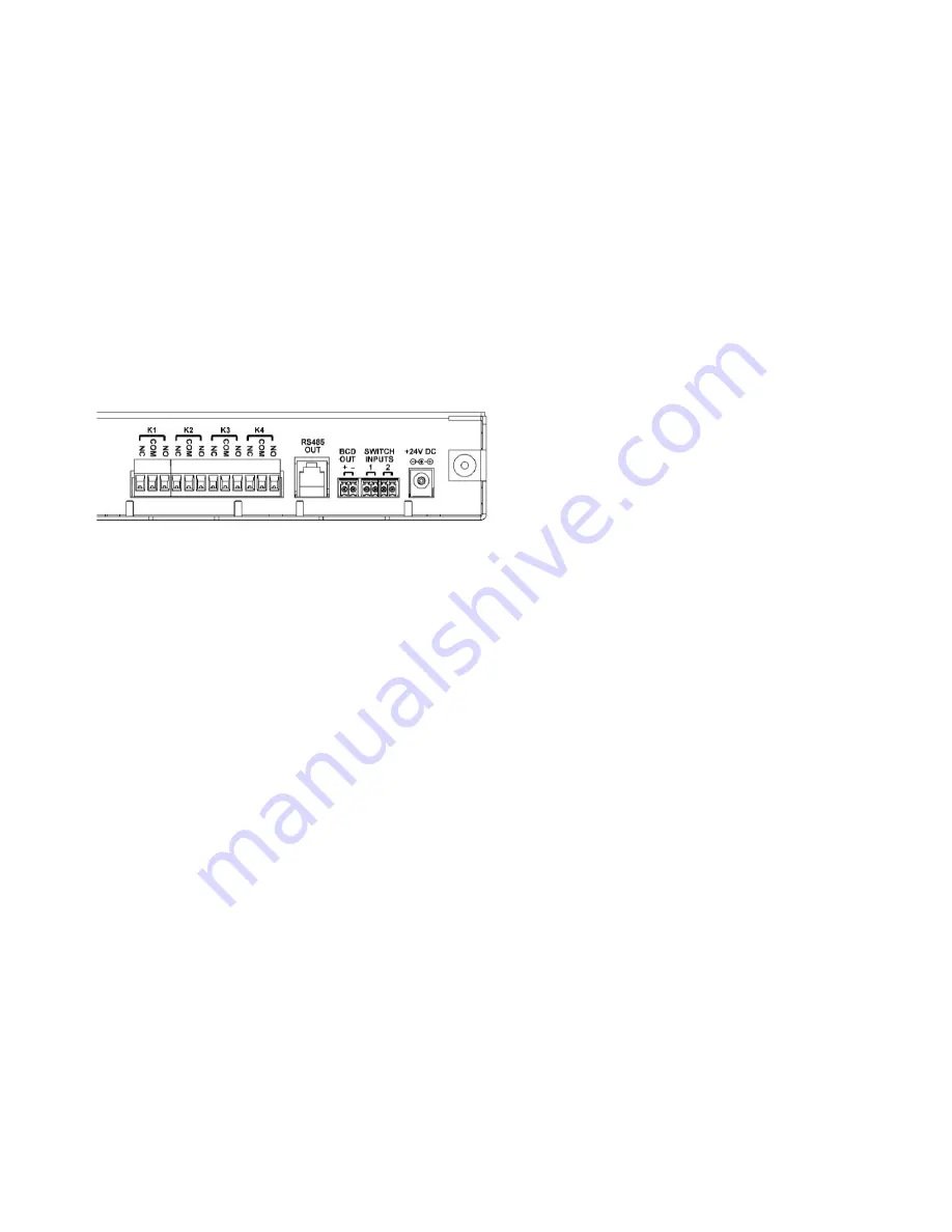
The VIP-MC signal connectors are on the rear
panel, as shown in Figure 1.
•
4 Form C relays
•
1 RS485 output
•
1 BCD output
•
2 Contact Closure switch inputs
•
1 24Vdc power input
Figure 1
K1, K2, K3, K4 Relays:
Four Form C relays are
available for clock control, supervision or general
usage depending on the programming options
selected. The screw terminal blocks are removable
for easier installation. The terminals are labeled for
Common (C), Normally Closed (NC) and Normally
Open (NO).
RS485 OUT:
The RS485 output connection
provides signaling for 2-wire Digital-Corrected
Clocks in a format suitable for direct input to a
Valcom V-CCU Clock Controller. The connector is
a 6-pin RJ11 with the signal appearing on the
center two pins (3 & 4). The output signal is the
same as a Valcom V-DCPI.
BCD OUT:
The BCD output connection provides
signaling for 2-wire BCD Corrected Clocks, typically
used with Simplex clocks.
SWITCH INPUTS 1 & 2:
The two Switch Inputs are
dry contact inputs which can be programmed to
manually control one of the relay outputs or to set
the system time. If provisioned for System Time,
the VIP-MC will be set to a user-specified time
when the contact is closed.
24V DC:
Barrel connector input jack for external
power.
SETUP
Programming
Information specific to your application must be
programmed into the VIP-MC. Programming can
be done using the front panel LCD control, using
the built-in web interface or using the Valcom VIP-
102B IP Solutions setup tool. For ease of access,
the PC used for programming should be connected
to the same subnet as the VIP-MC. Download the
latest version of the free IP Solutions Setup Tool
from the Valcom web site at
www.valcom.com/vipsetuptool
The VIP-MC is programmed at the factory to
acquire an IP address using Dynamic Host
Configuration Protocol (DHCP). If the DHCP scope
includes Option 42 (NTP Server) and either Option
100 or Option 101 for time zones, the VIP-MC will
operate using those values. If DHCP is not
available, the VIP-MC will revert to the static IP
address of 192.168.6.207 after 3 minutes.
Factory Reset
The VIP-MC can be reset to Factory default
programming using the front panel LCD control.
Two levels of reset are available. Press and hold
the OK button for 10 to 19 seconds to reset the
Network settings. Holding the OK button pressed
for more than 20 seconds will reset all programming
(including passwords).
TECHNICAL ASSISTANCE
When trouble is reported, verify power is being
supplied to the unit and there are no broken
connections. If a spare unit is available, substitute
a spare unit for the suspected defective unit.
Assistance in troubleshooting is available from the
factory. Call (540) 563-2000 and press 1 for
Technical Support or via email at
support@valcom.com. When requesting
assistance, you should include all available
information. It is strongly suggested that you go to
the web site and review the information at
www.valcom.com.