background image

- 55 - 


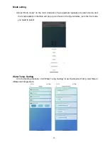
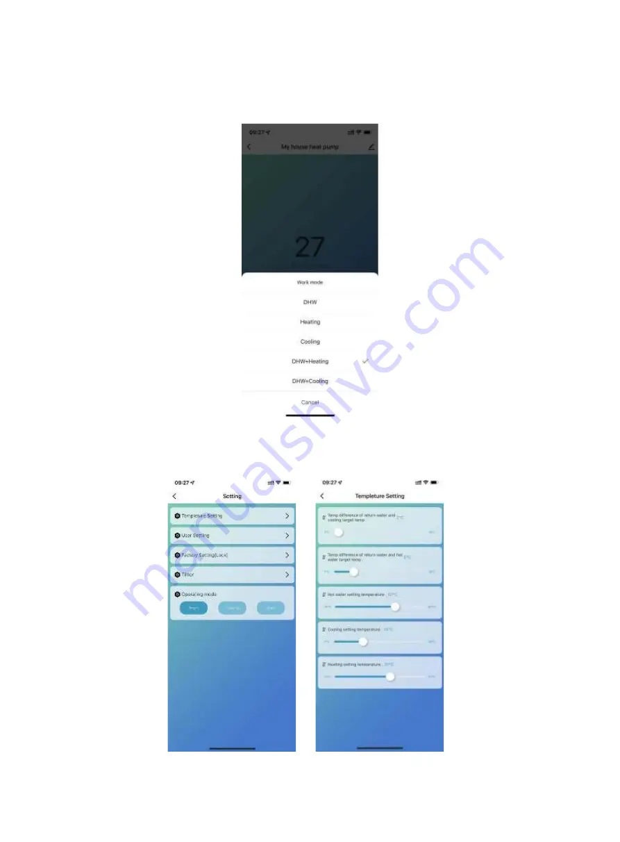
Mode setting 


Click "Work mode" on the main interface of the equipment operation to switch mode, and 

the mode selection interface will pop up as shown in the figure below, just click the mode 

you need to select. 


Water Temp. Setting 

In the Setting interface, 

click“Water

 Temp. 

Setting”

 to set the Desired Temp. And Return 

difference Temperature 

Summary of Contents for V1 Series

Page 1: ...VI DC Inverter Heat Pump with WIFI APP OPERATING INSTRUCTION MANUAL Valdemar Energy Denmark www valdemarenergy com IMPORTANT SAFETY INSTRUCTIONS READ AND FOLLOW ALL INSTRUCTIONS SAVE THESE INSTRUCTION...

Page 2: ...unding and Over Current Protection 21 Electrical Wiring Diagram 22 Section 3 Operating Heat Pump 25 Controller Panel 25 1 Display Icon 25 2 Definition of Buttons 26 3 Wire Controller Operation 27 Gene...

Page 3: ...cal codes take precedence over national codes In the absence of local codes refer to the latest edition of the National Electric Code NEC in the local government Electric Code CEC for installation Ris...

Page 4: ...nstaller or service agent and must conform to all national state and local codes and or safety regulations 2 This EVI DC Inverter Air Source Heat Pump is specifically designed for domestic hot water h...

Page 5: ...Inverter air source heat pump Note Before installing this product read and follow all warning notices and instructions Only a qualified service person should install the heat pump Materials Needed fo...

Page 6: ...t R32 1 3kg R32 1 6kg Compressor Brand Panasonic IP Grade Level of Protection IPX4 IPX4 Anti electric Shock Rate I I Noise dB A 53 55 Water Pressure Drop kPa 31 25 Water Circulation m H 1 4 2 2 Diamet...

Page 7: ...onic IP Grade Level of Protection IPX4 IPX4 IPX4 IPX4 Anti electric Shock Rate I I I I Noise dB A 57 58 62 66 Water Pressure Drop kPa 35 45 40 45 Water Circulation m H 3 1 4 0 4 8 6 0 Diameter of Pipe...

Page 8: ...ical connections 2 Field assembly if required 3 Appropriate site location and clearances 4 Proper electrical wiring 5 Adequate water flow This manual provides the information needed to meet these requ...

Page 9: ...8 V1 18 V1 23 V1 28 V1 35...

Page 10: ...9 Exploded view V1 08...

Page 11: ...10 V1 13...

Page 12: ...11 V1 18 23...

Page 13: ...12 V1 28 35...

Page 14: ...proximity to public access areas The heat pump must be placed to provide clearances on all sides for maintenance and inspection 1 The heat pump installation area must have good ventilation and the air...

Page 15: ...times Suggested Installation Methods 1 For heating hot water installation 1 System installation diagram see Figure 2 2 Electrical wiring diagram see Figure 3 If you don t install auxiliary heating DO...

Page 16: ...15 Figure 2 Figure 3...

Page 17: ...iring diagram see Figure 8 If you do not need to install auxiliary heating DO not connect point 1 4 AC contactor 3 Controller panel setting see Figure 9 4 Terminal of 3 way valve is not needed for wir...

Page 18: ...17 Figure 7 Figure 8...

Page 19: ...ot connect point 1 4 AC contactor 3 Controller panel setting see Figure 12 and Figure 13 The inlet water setting temp of the heating or cooling mode can be adjusted by Target temperature setting inter...

Page 20: ...19 Figure 11 Figure 12 Figure 13...

Page 21: ...age and pressure test 4 All the pipelines and pipe fittings must be insulated to prevent heat loss 5 Install a drain valve at the lowest point of the system to enable the system to be drained during f...

Page 22: ...dards to select the cables circuit breakers and isolator breakers Grounding and Over Current Protection In order to prevent electrical shock in case of leakage from unit install the heat pump accordin...

Page 23: ...22 Electrical Wiring Diagram 1 Single phase system V1 08...

Page 24: ...23 2 Three phase system V1 13 18 23...

Page 25: ...24 3 Three phase system V1 28 35...

Page 26: ...tons in orange 1 Display Icon Mode Meaning Heating mode Hot water mode Cooling mode Heating and Hot water Mode Hot water function as priority Cooling and Hot water Mode Hot water function as priority...

Page 27: ...ture of heating cooling at heating hot water mode cooling hot water mode Temp display real time water tank temperature at only hot water mode or real time return water temperature of heating cooling a...

Page 28: ...in interface press MODE button for around 1 seconds to switch the running modes 5 modes optional heating only cooling only DHW only heating hot water cooling hot water Under heating hot water mode or...

Page 29: ...ormal mode Heat pump has Smart Powerful Silent Operating states to choose Vacation mode description When this mode is enabled the heat pump runs in heating mode only with a Target temperature of vacat...

Page 30: ...d exit or press Esc toexit without saving CLOCK SETTING In the main interface press to enter clock setting interface as below Press the date Year Month Day column or hour Hour Minute column the keyboa...

Page 31: ...perform on that day When the weekday button turns gray the timer will not perform on that day In the TIMER column users can set 4 pairs of timers at maximum The timer is invalid when the turn on time...

Page 32: ...ening of assistant expansion valve 13 Compressor current 14 Heat sink temp 15 DC bus voltage value 16 Compress actual frequency 17 Low pressure gauge pressure value R410 Real time data Bar 18 High pre...

Page 33: ...temp 15 50 35 P06 Setting temp of exhaust gas too high protection TP4 50 125 120 P07 Setting temp of exhaust gas too high recover tp0 50 125 95 P08 Water temp compensation 5 15 inlet outlet water wate...

Page 34: ...ressor s Frequency operation mode after constant Temperature 0 Decrease Frequency after constant Temp 1 Non Decrease Frequency after constant Temp 0 P26 Pipeline E Heater Enable Ambient Temp 20 20 0 P...

Page 35: ...temperature Antisepsis program will be forced to exit Target Temperature Auto Adjustment Logic Under Heating Mode The target temperature under heating mode can be automatically adjusted according to t...

Page 36: ...emp P05 Restart difference P01 4 Water pump during Working States When the above conditions are met The Electric Heater will turn on Shut down condition 1 Under Cooling or Hot Water Mode 2 Without Hea...

Page 37: ...before leaving factory don t adjust it by yourself 2 2 Unit have enough refrigerant and lubricating oil don t fill or replace them if filling is needed to prevent leakage please refer to the quantity...

Page 38: ...37 use G If the unit is soaking please contact the supplier factory or company of installment before use...

Page 39: ...e the record in the FAULTY column inside the SETTING interface The following Common Error Codes will be displayed on the controller panel Error Code Definition of Error or Protection Er 03 Water flow...

Page 40: ...Too high pressure protection When there s Er 20 error in the system it will display below detailed error code from 1 to 348 Among them 1 128 are in the first class and will be displayed aspriority 25...

Page 41: ...le is effective Inspection input circuit 260 AC Input over current Input three phase imbalance three phase module is effective Inspection input three phase phase voltage 264 AC Input low voltage Input...

Page 42: ...ase turn off the heat pump and disconnect it from the main power supply when not in use for a prolonged lifetime Troubleshooting Use the following troubleshooting information to resolve issues problem...

Page 43: ...is normal or not Check the pipe splice and the air injection valve whether have grease or dirt Make sure there s no refrigerant leakage in the cooling system 7 Don t stack any sundries around the unit...

Page 44: ...ean the water filter Compressor not working Power failure Contactor of compressor damage wiring loose Compressor overheat protection outlet water temp Too high Not enough water flow Compressor overloa...

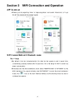
Page 45: ...n be connected within 10s after the first power on and it needs to be connected by pressing buttons after 10 seconds 10s is the delay for Wi Fi to enter low power consumption Manually enter the smart...

Page 46: ...luetooth Turn on the WIFI function of the mobile phone and connect to the WIFI hotspot The WIFI hotspot must be able to connect to the Internet normally as shown in the figure Connect the WIFI hotspot...

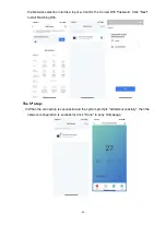
Page 47: ...Input Confirm the Correct Wifi Password Click Next tostart Matching Wifi The 5th step When the connection is successful and the system prompts Added successfully then the network configuration is succ...

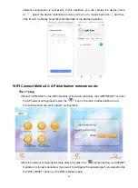
Page 48: ...RESET to enter the smart distribution mode the icon on the main interface flashes and the mobile phone can start to configure the network Exit the network configuration status after 3 minutes the ico...

Page 49: ...ce type selection and select Water Heater in the Large Home Appliance to enter the add device interface The 4th step After selecting the water heater enter the Add Device interface confirm that the wi...

Page 50: ...ile phone and click Next to directly enter the device connection state Remarks When the wired controller s WIFI module is connected to the WIFI hotspot the icon flashes fast The 5th step When the Scan...

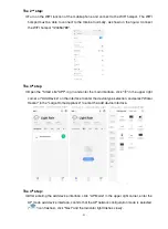
Page 51: ...tion network mode The 1st step Select AP MODE on the WIFI interface of the wired controller click WIFI RESET to enter the AP network configuration mode the icon on the main interface flashes and the m...

Page 52: ...d enter the main interface click in the upper right corner or Add Device on the interface to enter the device type selection and select Water Heater in the Large Home Appliance to enter the add device...

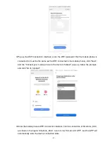
Page 53: ...bile phone click Next and the Connect your mobile phone to the device s hotspot pops up follow the prompts and click Go to Connect Enter the mobile phone s WIFI connection interface find the connectio...

Page 54: ...on is successful and the system prompts Added successfully then the network configuration has been done correctly In this interface you can change the device name at select the device installation loc...

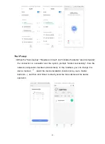
Page 55: ...ouse Heat Pump device s operation page return Fault information display fault information when a fault occurs More You can change the device name select the device installation location check the netw...

Page 56: ...ent operation to switch mode and the mode selection interface will pop up as shown in the figure below just click the mode you need to select Water Temp Setting In the Setting interface click Water Te...

Page 57: ...if the water tank temperature 55 both the compressor and electric heater will start When the water tank temperature 70 and the protection temperature lasts for 30minutes 65 exit the high temperature...

Page 58: ...ry Electric Heater for Water Tank Start conditions all below conditions must be met at the same time 1 In hot water mode 2 The compressor runs start time for electric heating of water tank 30 minutes...

Page 59: ...nlet Water Temp Heating Set Temp P05 Restart difference P01 8 Water pump during Working States When the above conditions are met The Electric Heater will turn on Shut down condition 7 Under Cooling or...

Page 60: ...ates in the following sequence After successful sharing the list will be increased and show the shared person To delete the shared person long press the selected user the delete interface will pop up...

Page 61: ...operate and control the device Device removal APP removal Click in the upper right corner of device operation main interface to enter device details interface and click Remove Device interface to ente...

Reviews: