


Service manual
7
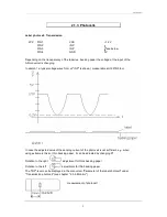
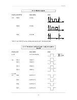
Dispensing photocell
JP4:
PIN 1
VCC
5 V
PIN 2
INP
see sketch
PIN 3
VSS
~ 1,2 V
PIN 4
GND
0V
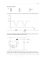
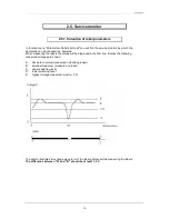
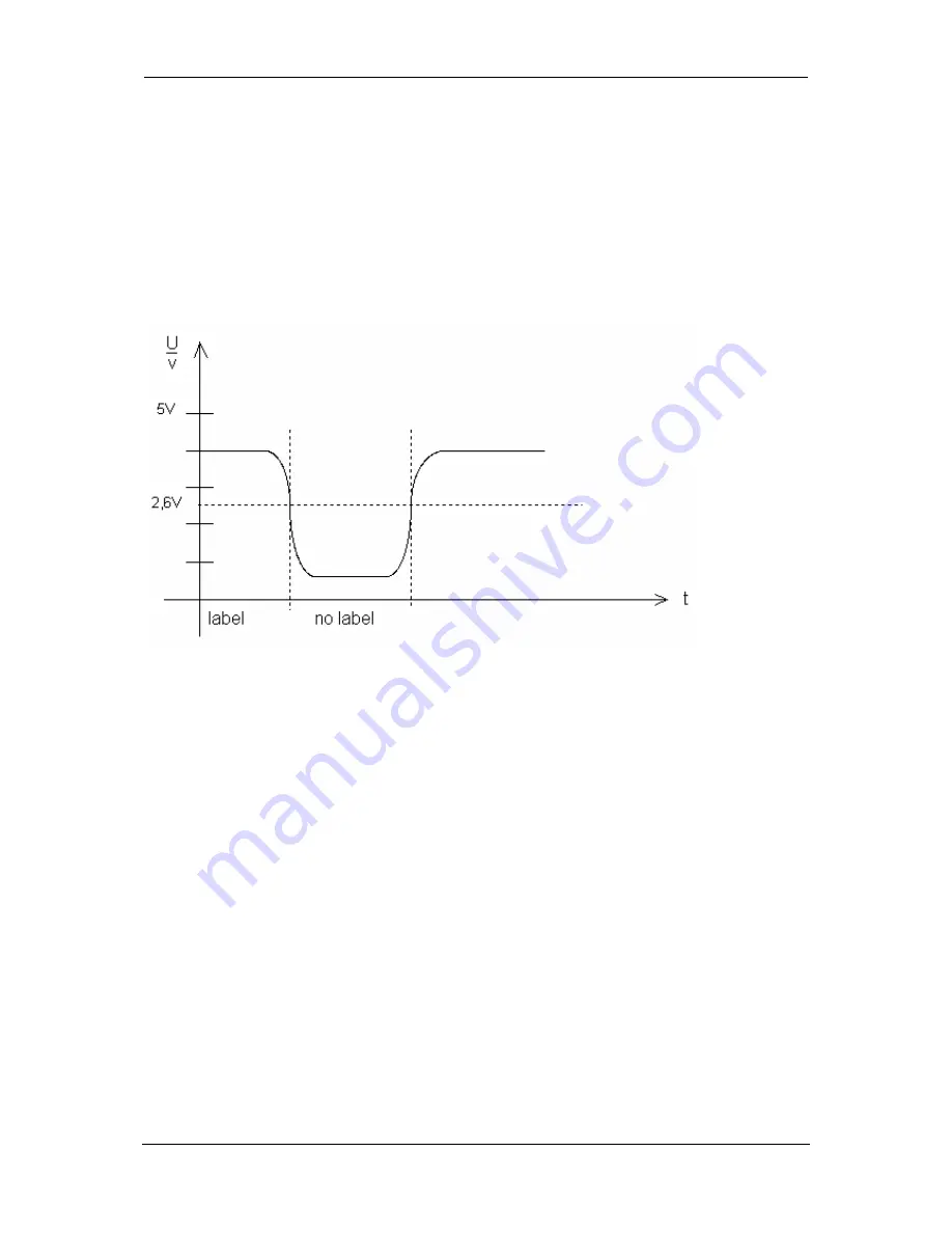
The typical voltage wave form at "INP" (measurable at U6 PIN 5 too) is shown in sketch 3.
As standard a level of 2,6 V is adjusted. If a label is under the dispensing photocell, the level at "INP"
must be higher than 2,6 V. If the label is being removed, the voltage must lower under 2,6 V.
In some cases it is necessary to change the level of the dispensing photocell. This can be done in the
menu "Printer initialization - LS-Dispenser level".
The "INP"-level can be displayed in the menu item "Parameter of the label photocell" under
"Dispensing photocell" (see chapter "2.5.4. Monitor").