


Service manual
12
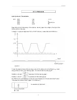
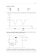
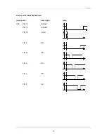
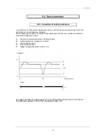
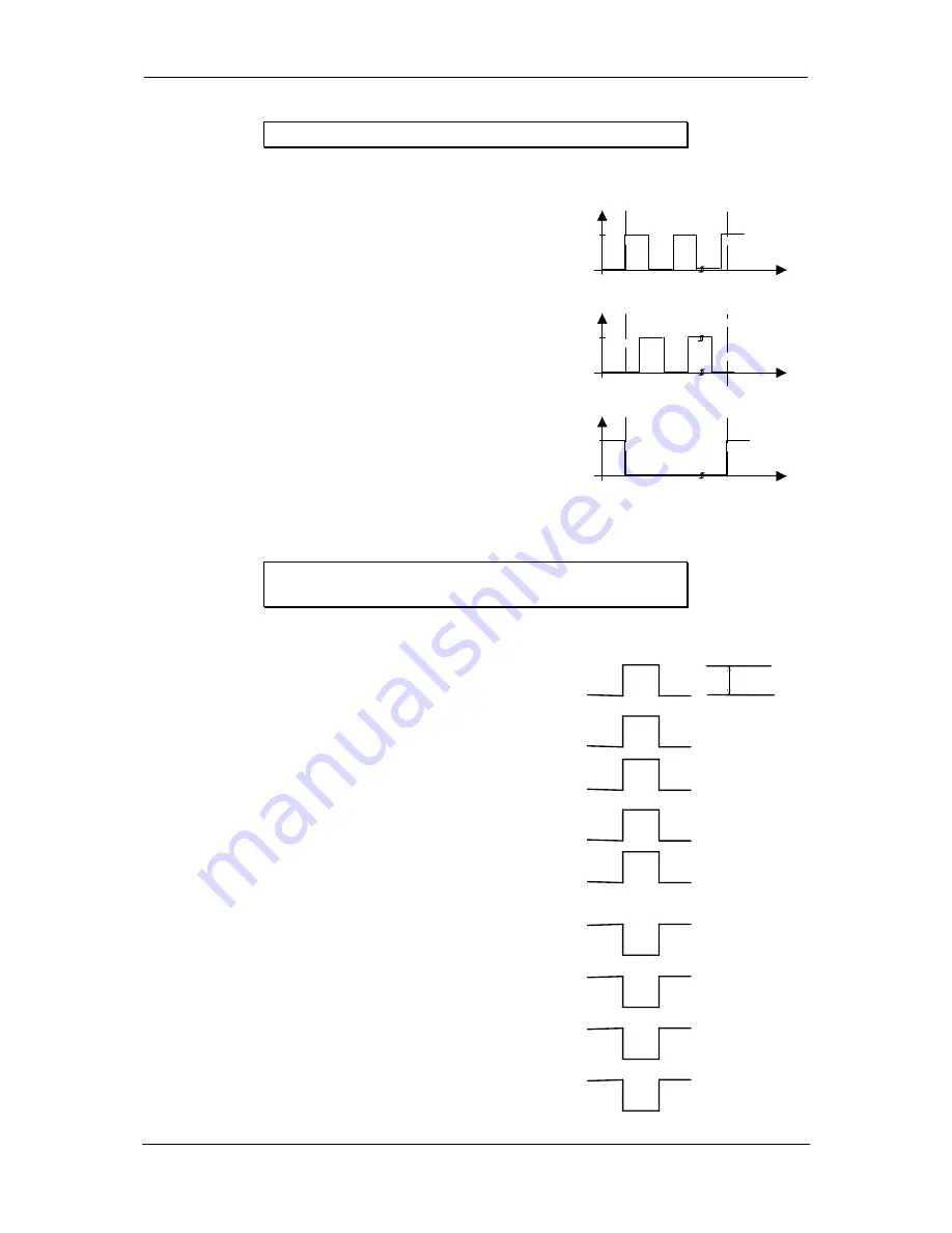
2.1.6. Motor signals
check point (CPU)
description
value
U15
PIN15
VOR A
5V
t
Motor ein
Motor aus
PIN12
VOR B
5V
t
PIN9
FR VOR
5V
t
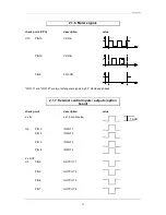
"VOR A" and "VOR B" are two rectangular signals by 90
°
displaced phases.
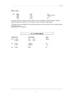
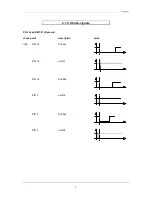
2.1.7. External control inputs / outputs (option
board)
check point
description
value
4 x IN
ext. input impulse
12-24V
U6
PIN 2
INPUT 1
PIN 4
INPUT 2
PIN 6
INPUT 3
PIN 8
INPUT 4
4 x OUT
U3
PIN2
OUTPUT 1
PIN3
OUTPUT 2
PIN6
OUTPUT 3
PIN7
OUTPUT 4


