background image


Service manual 


15 

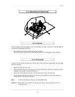
2.4. Changing of fuses 


2.4.1. Primary fuse 


solo rear panel: 

The primary fuse is in the power line filter block and 
accessible from outside. 
After plugging out, the cover can be removed. There 
behind you will find the fuse-switch, which has to be 
drawn near to change the fuse. 

F: fine-wire fuse T1,0A 


power line filter block 

F


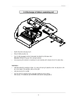
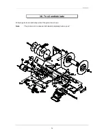
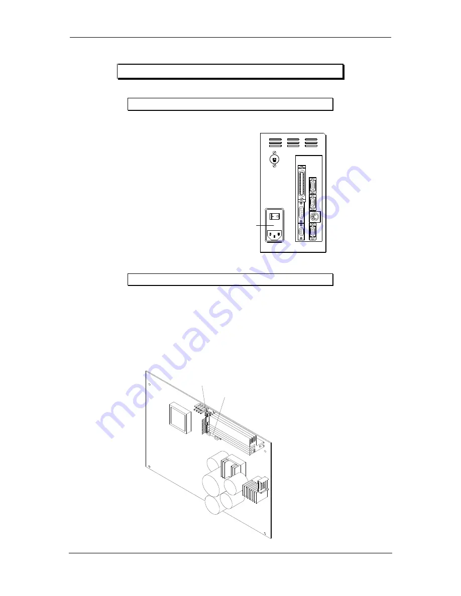
2.4.2. Secondary fuse 


Attention: 

The machine should be opened by competent staff only. 
Pug out before removing the left cover. 

 
After removing the left cover the base plate is visible, whereon you will find two secondary fuses. 


F1: fine-wire fuseT 1,0 A 

fuse for 5 V and 12 V supply (CPU) 

F2: fine-wire fuseT 6,3 A 

fuse for motor voltage (35 V) and burning voltage (18 V res. 21 V) and 
12 V supply (fan) 


F1

F2


Summary of Contents for Solo type

Page 1: ...English Service manual Thermal Transfer Printer Solo type 79 25 025 12 December 1997 Carl Valentin GmbH Neckarstra e 78 80 94 78056 VS Schwenningen support valentin carl de http www valentin carl de...

Page 2: ......

Page 3: ...y fuse 15 2 5 Service monitor 16 2 5 1 Valuation of label parameters 16 2 5 2 Error message label error 17 2 5 3 Error elimination 18 2 5 4 Monitor 18 3 Mechanics 19 3 1 Exchange of print head 19 3 2...

Page 4: ......

Page 5: ...Service manual 1 1 Block circuits 1 1 Block circuit baseboard CPU network The corresponding plan is available on demand...

Page 6: ...Service manual 2 1 2 Block circuit option board The corresponding plan is available on demand...

Page 7: ...Service manual 3 1 3 Wiring diagram The corresponding plan is available on demand...

Page 8: ...VDD 5V JP6 7 PIN 32a c GND 0V JP24 PIN 1 3 VH 18V printhead solo 51 21V printhead solo 80 JP24 PIN 4 6 GND 0V JP30 PIN 1 12V 12V JP25 PIN 1 VM 35V R47 upper PIN VG 35V R47 lower PIN VR 7 2V 2 1 2 Volt...

Page 9: ...INP is shown measurable at U6 PIN3 too In case the adjusted value of the sending current of the photocell is not sufficient e g when using extremely thick or thin backing paper it can be adjusted by...

Page 10: ...asurable at U6 PIN4 too It has to be considered that the marking for the reflection photocell must be in a distance of 32 5 mm to the interior rim so that the photocell recognizes the marking The INP...

Page 11: ...a label is under the dispensing photocell the level at INP must be higher than 2 6 V If the label is being removed the voltage must lower under 2 6 V In some cases it is necessary to change the level...

Page 12: ...has been properly loaded the photocell is sending a Low signal if there is no ribbon a High signal The INP level can be displayed in the menu item Parameter of the photocell under transfer ribbon pho...

Page 13: ...e manual 9 2 1 5 Strobe signals Print head KMT 51 Kyocera check point description value U24 PIN 14 Strobe1 5V t PIN 12 Latch1 5V t PIN 16 Strobe2 5V t PIN 5 Latch2 5V t PIN 9 Strobe3 5V t PIN 7 Latch3...

Page 14: ...vice manual 10 Print head FP 80 8X Mitsubishi check point description value U24 PIN 14 Strobe1 PIN 16 Strobe2 5V t PIN 18 Latch 5V t PIN 9 GA 5V t PIN 12 GB 5V t PIN 5 GC 5V t PIN 7 GD 5V t PIN 3 GE 5...

Page 15: ...11 Print head KHT 80 8MPU1 VA Kyocera check point description value U24 PIN 14 Strobe1 5V t PIN 16 Strobe2 5V t PIN 18 Latch 5V t PIN 9 CONT1 5V t PIN 12 CONT2 5V t PIN 5 CONT3 5V t PIN 7 CONT4 5V t P...

Page 16: ...V t PIN9 FR VOR 5V t VOR A and VOR B are two rectangular signals by 90 displaced phases 2 1 7 External control inputs outputs option board check point description value 4 x IN ext input impulse 12 24V...

Page 17: ...Service manual 13 2 2 Component parts of baseboard The corresponding plan is available on demand...

Page 18: ...Service manual 14 2 3 Component parts of option board The corresponding plan is available on demand...

Page 19: ...ear to change the fuse F fine wire fuse T1 0A power line filter block F 2 4 2 Secondary fuse Attention The machine should be opened by competent staff only Pug out before removing the left cover After...

Page 20: ...labels the values will be displayed in the first line thereby the following measured voltages are shown A absolute minimum measured on backing paper B smallest maximum measured on label C upper switc...

Page 21: ...d backing paper Very thin labels In this case the value of E res B is too low so the printer cannot distinguish between backing paper and labels Pre printed label with strong differences in contrast P...

Page 22: ...e last character shows the position of the photocell above label above backing paper 0 at the edge label backing paper The monitor serves to check the label photocell to its function As well it is pos...

Page 23: ...counter clockwise Pull off print head plug C including cable and take it off through the sheet iron opening Take off locking washer D Dislocate the hook of the brake spring E by means of a screwdriver...

Page 24: ...int shows irregularities the print quality has to be adjusted Switch off printer and plug it out At first remove 2 screws on the bottom of the printer and the lock in bolts for the right cover at the...

Page 25: ...e turn the print head manually but carefully up Clean the print head only with dry cleaning solvent As expedient a close woven cotton cloth is recommended In case this procedure is not sufficient the...

Page 26: ...r clockwise Loosen 2 locking screws E1 E2 of the cogged belt drive Remove 2 safety washers G1 G2 from the rolling shaft Press pressure roll H inwards and draw external ball bearing I off the rolling s...

Page 27: ...l plate In case spring C remains in unwinding roll pull it outside with rotary motion at the same time Installation Lubricate pillar D according to chap 3 6 and push spring if possible a new one appro...

Page 28: ...Service manual 24 3 6 To oil and lubricate Following all oil and lubricate points of the printer are shown Note The printer is to be oiled and lubricated completely twice a year...

Page 29: ...e chassis then take off left cover Plug out JP4 on the circuit board see specification on circuit board and cable photocell Remove screws A1 A2 Remove dispenser in doing so guide photocell cable B wit...

Page 30: ...ove screws A1 A2 Take off cutter In doing so guide cable J with plugs through the slot on the bottom of the chassis After having removed the screws C1 C2 take off the angular stay Lever the upper cove...

Page 31: ...nd draw off bearing I to the front After having released the locking screws J1 J2 draw off carrier plate K Remove cover cap L take off condenser and photocell cable on the back of the motor by using a...

Page 32: ...the top edge of the chassis then take off left cover In case circuit board A is fixed with 4 cylindrical head screws replace them by 4 spacer bolts B according to drawing Introduce MC plug in unit C i...

Page 33: ...ecutive numbers incorrect entry of consecutive numbering check entry of consecutive numbering and change magnification code entered SC factor is invalid check SC factor and change width lines or boxes...

Page 34: ...bel name already stored on Memory Card change label name no label exists label name not stored on Memory Card search through the contents of the Memory Card and select the desired name unknown error i...

Page 35: ...le print mode Cutter OFF or connect cutter cutter cutter will not be switched off cutter photocell or micro switch are defective Please contact your distributor power failure please wait loss of volta...

Page 36: ...int print head is badly adjusted see chapter 3 2 Adjustment of print head irregular print pressure finger in wrong position relocate finger as long as print is regular no print incorrect voltage suppl...

Page 37: ...pter 2 1 3 Photocells no transport of labels cogged belt torn motor res motor activation defective exchange cogged belt see chapter 2 1 6 Motor signals transfer ribbon is not rewound vulcollan drive b...

Page 38: ...r 3 5 Exchange of ribbon unwinding roll guiding shaft for ribbon is bent shaft must be adjusted so that ribbon stops creasing If this is not possible return printer for repair pressure roll is run in...

Reviews: