807
Thermo AC/DC
8 Repairs
NOTE:
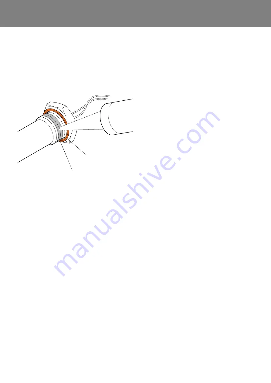
The groove of the gasket ring must in installed position
rest on the heat exchanger.
3. Apply thread sealant according to the manufacturer‘s
instructions onto the thread, see
, of the hea-
ting cartridge (1,
) or the screw plug
(3).
4. Screw the heating cartridge (1) or the screw plug (3)
into the heat exchanger.
5. Tighten the heating cartridge (1) or the screw plug (3)
as required.
6. Install the small distribution board (see
).
8.7
HV wiring harness (AC/DC) removal/
installation
Removal
1. Establish voltage-free state of the heater and secure
it for duration of the work (
Observe
)
2. Disconnect all supply cables from vehicle electrical
system.
3. Remove housing (see
4. Remove ties wich bundle disconnected wires.
NOTE:
During the next step pay attention that the cables are not
jammed or are still connected. “Danger of damage“.
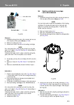
5. Loosen cable gland (4,
) and screw
it with the appropriate cable harness from out the hou-
sing (17).
Installation
NOTE:
During the next step pay attention that the cables are not
jammed. “Danger of damage“.
1. Route the single wires of the HV wiring harness
through the appropriate hole (see
into the housing (17) and screw the cable gland (4)
into the housing and tighten it.
2. Install housing (see
3. Check the wiring again using the appropriate wiring
diagram in Chapter
4. Bundle single wires using cable ties.
5. Install hood (see
6. Connect all supply cables to the vehicle electrical sys-
tem, fix them if required.
7. Perform a function check.
8.8
LV DC control wiring harness
removal/installation
Removal
1. Establish voltage-free state of the heater and secure
it for duration of the work (
Observe
!
)
2. Disconnect all supply cables from vehicle electrical
system.
3. Remove housing (see
).
4. If necessary disconnect connectors from the HVIL
socket.
5. Remove ties wich bundle disconnected wires.
6. Separate single wires at the end connectors and the
depending on the heater version).
NOTE:
During the next step pay attention that the cables are not
jammed or are still connected. “Danger of damage“.
7. Loosen cable gland (5,
) and screw
it with the appropriate cable harness from out the hou-
sing (17).
Installation
NOTE:
During the next step pay attention that the cables are not
jammed. “Danger of damage“.
1. Route the single wires of the LV DC control wiring
harness through the appropriate hole (see
) into the housing (17) and screw the cable
gland (5) into the housing and tighten it.
2. Connect single wires as required with end connectors
(see
depending on the heater
version).
3. Install housing (see
Fig. 806
Gasket ring
Thread sealant
(over 3 threads centered)
Summary of Contents for Thermo AC 070
Page 47: ...memos...


