Installation
Thermo DC 200
8
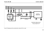
Figure 4: Connecting schematic with integrated DC-DC converter (Thermo DC compact distributor board)
4mm², GR, 180mm, Radox 3 GKW 12545290
0,75mm², RT, 200mm, FLRY
Schütz Siemens
3TC4417/0AB4
2,5mm²,
R
T,
250mm
2,5mm²,
R
T,
250mm
QUINT/PS/ 3AC/
24DC
Radox 3 GKW 12545290
4mm², GR, 180mm,
SW
BL
BR
RT
1
1
2
2
3
4
68 ... 75 °C
125 °C
M12x1,5
1
7
2
8
3
9
4
10
5
11
6
12
14
14
-
-
-
16
13
17
18
19
20
13
13
DC
OK
15
+
N
+
+
L1
L2
L3
GND
2
T1
4
T2
A2
24-
4mm²,
R
T
4mm²,
S
W
1
L1
3
L2
A1
24+
Cable colors
SW
black
BL
blue
BR
brown
GN
green
GR
grey
OR
orange
RT
red
GNGE
green/
yellow
690 VDC
Note the prescribed
means of protection!
- overcurrent protective device
see Section “Installation“, Figure 8
Note: Heater internal connections not shown.
Load
Contactor
Summary of Contents for THERMO DC 200
Page 4: ...IV Thermo DC 200...
Page 34: ...Technical data Thermo DC 200 30 For notes...
Page 35: ...memos...


