27
Thermo DC 200
Annex
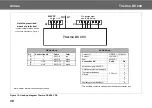
Figure 13: Hook-up diagram Thermo DC 486V DC
2 1
1
5
3
7
2
6
4
8
X2
X1
HV LV
Thermo DC 200
690V DC
Note the prescribed
means of protection!
- overcurrent protective device
see Section “Installation“, Figure 5
Note: Heater internal connections not shown.
HV Hook-up
LV Hook-up
Connection HU
Cable
Color
Connector
HDSCS 1-1418479-1
+
6 mm²
red
Contact
1241380-1
-
6 mm²
black
Seal
963530-1
Connection HU
Cable
Pin
0.75 mm²
1
Activation signal 600V DC
2
Overheat protection feedback
3
Thermostat feedback
4
Ground
5
6
Auxiliary contact input *
7
Auxiliary contact feedback *
8
Pin assignment
see table below
486V DC
* The auxiliary contact is closed when the heater/contactor is on.
Summary of Contents for THERMO DC 200
Page 4: ...IV Thermo DC 200...
Page 39: ...memos...


