33
Thermo DC 200
Annex
13.4. Differing installation instructions for Thermo DC
11125620_
690 VDC supply line
The hook up must be made with at least a cable corresponding to the
heater connection cable (HV). The cable cross-section must be chosen
according to the power and installed cable length.
Use a dedicated power circuit for the heating system.
The appliance must have a fixed connection to the DC power supply.
The heating appliance must be connected to the potential equalization.
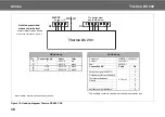
The connection must be carried out in accordance with the enclosed
hook-up diagram (see Figure 17).
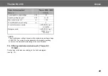
Technische Daten Thermo DC 11125620_
Heater (electrical system)
Thermo DC200
(690V)
Ident. no.
11125620_
Nominal heating flow
kW
20
Nominal voltage
VDC
690
Frequency
Hz
--
Nominal current
A
29.6
Rated current at 540V DC
A
23.3
Rated current at 690V DC
A
29.6
Rated current at 750V DC
A
32.2
Rated current at 900V DC
A
38.6
Type of electrical protection
1000V DC/xxA/10kA
fast-blow
Circuit breaker rating
A
50*
Operating voltage range HV
VDC
0 - 900
Cross section HV supply cable
mm²
6
HV wiring harness at heater side
Ring type terminal end
8mm/10mm²
Min. cable cross section at
vehicle side
mm²
6
Insulation resistance new device at
1000V
M
Ω
>100
Insulation resistance end of life at
1000V
M
Ω
>50
Control signal nominal voltage
VDC
24
Operating voltage range LV
VDC
16 - 32
Max. control current LV
A
1.58
LV circuit breaker current rating
A
5
LV control harness connector
AMP HDSC 8 pin 1-
1418479-1
Mating connector
AMP HDSC 8 pin 1-
1564416-1 o. 1-
1564512-1
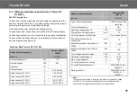
*
Note:
The circuit breaker rating is based on the maximum operating voltage
of 900V DC. The rating must be adapted to the highest operating
current and the temperature derating of the circuit breaker.
Heater (electrical system)
Thermo DC200
(690V)
Ident. no.
11125620_
Summary of Contents for THERMO DC 200
Page 4: ...IV Thermo DC 200...
Page 39: ...memos...


