402
Thermo E+ 120/200/320
4 Heater functions
4.2
Operational heater sequence
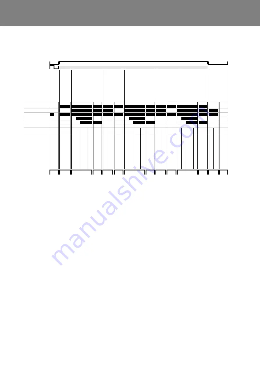
4.2.1 Switching on and start
When switched on, the operating display is illuminated,
the control unit starts controlled operation and checks the
coolant temperature.
If the coolant temperature is below the upper temperature
threshold, the initial cycle starts.
Combustion air fan and circulating pump are switched on.
After approximately 12 seconds (initial cycle time) the
high-voltage spark is ignited. Approx. 1 second later the
solenoid valve of the fuel pump is opened.
The fuel injected via the atomizer nozzle and mixed with
the air of the combustion air fan, is ignited by the ignition
spark and burned in the combustion chamber.
The flame is monitored by a flame detector integrated into
the control unit.
Approximately 5 seconds after a flame is detected, the
control unit switches the electronic ignition unit off. Until
then the flame is stabilized.
With optional nozzle block preheater:
The heating element is in the control device in parallel
connected with the motor output and is activated by the
thermostat at temperatures below 0°C.
4.2.2 Heating operation
After the flame is stabilized, the heater is in controlled
operation.
Once the upper switching threshold is exceeded, heating
operation is finished and purge cycle initiated.
The solenoid valve is closed, the flame expires, however
the combustion air fan and circulating pump continue
running.
The purge cycle ends approx. after 120 seconds. The
combustion air fan is switched off.
The heater is in a controlled break. The operation indi-
cator is illuminated.
Once the temperature falls short of the lower switching
threshold, the heater restarts burner operation. It runs
through the same sequence as the switching-on
sequence.
Abb. 401 Operational sequence
Processes
Signals
Main switch
off
on
off
UPFA
Coolant temperature
T > T_US
T < T_US
T >= T_OS
T < T_US
T >= T_OS
T < T_US
Actuators
Operating display
Combustion air motor
Circulating pump
Electronic ignition unit
Solenoid valve
Time in s
12* 1
0..15
5
...
30
90
12* 1
0..15
5
...
30
90
12* 1
0..15
5
...
30 90
State
L
ook
for
In
iti
al
cy
cl
e w
ith
li
gh
t ch
ec
k
P
re-
ign
iti
on
Igni
tion
S
tab
ili
za
tio
n
P
urge c
yc
le
1 wi
th s
afe
ty
p
eriod
P
ur
ge c
yc
le
2
In
iti
al
cy
cl
e w
ith
li
gh
t ch
ec
k
P
re-
ign
iti
on
Igni
tion
S
tab
ili
za
tio
n
P
urge c
yc
le
1 wi
th s
afe
ty
p
eriod
P
ur
ge c
yc
le
2
In
iti
al
cy
cl
e w
ith
li
gh
t ch
ec
k
P
re-
ign
iti
on
Igni
tion
S
tab
ili
za
tio
n
P
urge c
yc
le
1 wi
th s
afe
ty
p
eriod
P
ur
ge c
yc
le
2
OFF
Standby
Start
Heating
Purge
cycle
Standby
Start
Heating
Purge
cycle
Standby
Start
Heating
Purge
cycle
OFF
*) The initial cycle state can be extended by up to 258 s (total initial cycle time up to 270 s) at low coolant temperatures due to preheating.
F
la
m
e
G
en
er
at
io
n
F
la
m
e
G
en
er
at
io
n
F
la
m
e
G
en
er
at
io
n
Summary of Contents for Thermo E+ 120
Page 64: ...memos...


