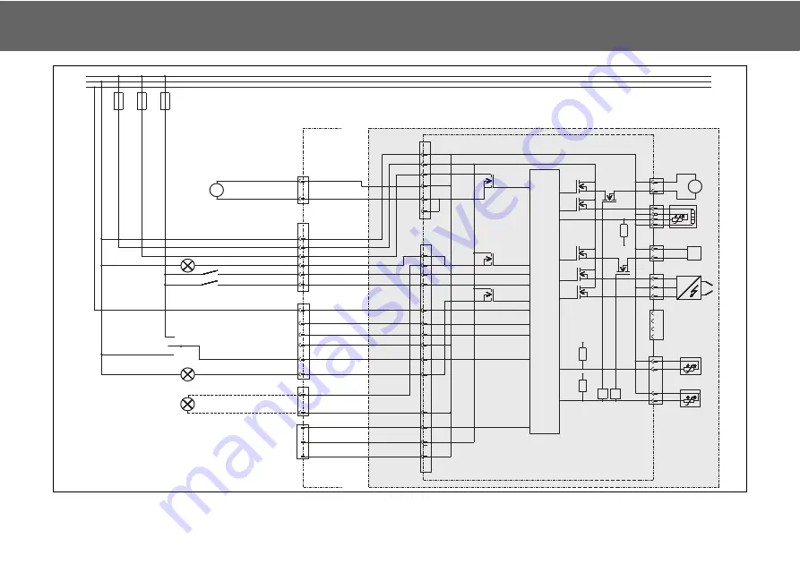
Hook-up (Diesel)
Thermo H
59
Fig. 6:
System wiring diagram for the Diesel burner head of the Thermo H, legend see page 58.
ZFG
SE
-
+
2
3
1
2
1
4
3
2
1
4
3
2
1
Coo
l
ant
O
verheating
2
1
1
4
3
2
MV
M
Z
M
R
T
V
B
BM
DVW
Contro
ll
er
V
cc
V
cc
V
cc
C
1
C
2
150
°
C
125
°
C
-50
°
C
1
2
3
5
4
6
13
5
8
9
14
7
2
3
4
10
6
1
11
12
A1
A2
1
2
0,75mm
0,75mm
0,75mm
0,75mm
0,75mm
BA +
BA -
D1
D2
W-BUS
S
Diagnostic
+
Diagnostic
-
BA (Test)
3
4
2
5
1
5
6
3
4
2
1
2
X2
X3
X1
0,75mm
0,75mm
0,75mm
0,75mm
0,75mm
0,75mm
0,75mm
2,5mm
2,5mm
2
.
5mm
2,5mm
2,5mm
UP -
UP +
M
UP 1
FA +
FA
O
peration
mode
S2
(three-pos
.
switch)
Eco
mode
2
Eco
mode
1
norma
l
K-Line
or
CAN-H
Termina
l
61
(D+)
HS
S1
S3
UPFA
BA
Termina
l
30(2)
Termina
l
30
(1)
Termina
l
31
BA +
30
31
61
F1
(HG)
F2
(UP)
F3
2
2
2
2
2
2
2
2
2
2
2
2
2
2
2
2
2
0,75mm
Diagnostic
-
0,75mm
L-Line
or
CAN-L
2
2
1
6
br
sw
br
rt
rt/ws
b
l
or
sw
rt/ws
rt
sw
br
or
rt
b
l
br
ge
rt
br
Contro
l d
e
vic
e
Heater
Heater
c
ab
l
e
harness
Summary of Contents for Thermo H
Page 85: ...memos ...


