16
3.3.2 Fuse Holder
The rear panel fuse holder provides access to the main power fuse. Fuse values are listed
below:
Fuse
Blo
Slo
Amp
Vac
Fuse
Blo
Slo
Amp
Vac
−
=
−
=
125
.
0
230
250
.
0
115
Replace blown fuses with their exact equivalent only!
3.3.3 Power Connector
The 3-prong power connector on the rear panel of the ohmmeter is for the application of
AC power to the instrument. The mating power cord is included with the instrument at
time of purchase. Refer to chapter 1 section 3 for available voltages and safety
precautions.
3.3.4 HLC Relay Terminal
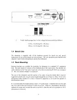
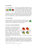
The HLC relay terminal is internally wired to
three relays which are active only when the
HLC mode is selected. According to the result
of the comparison, one of the relays will have
its contacts close while the remaining two
relays will have contacts open. The standard
"relay contact closure" feature allows an
automated sorting process to be set up at an
economical cost. The screw type terminal
allows connections to wires or spade lugs.
Contacts are rated at 100 volts, 100mA. Truth table of the contacts is listed below.
Ω
’s
symbol represents the load measured value, UL is the upper limit and LL is the lower limit
set by the user.
Table 6 - HLC Truth Table
HLC STATE
HLC RESULT
XLO
GO
XHI
ON
LL
≤Ω≤
UL
OPEN
CLOSED
OPEN
ON
Ω
<LL
CLOSED
OPEN
OPEN
ON
UL<
Ω
OPEN
OPEN
CLOSED
OFF
LL
≤Ω≤
UL
OPEN
OPEN
OPEN
OFF
Ω
<LL
OPEN
OPEN
OPEN
OFF
UL<
Ω
OPEN
OPEN
OPEN


