background image


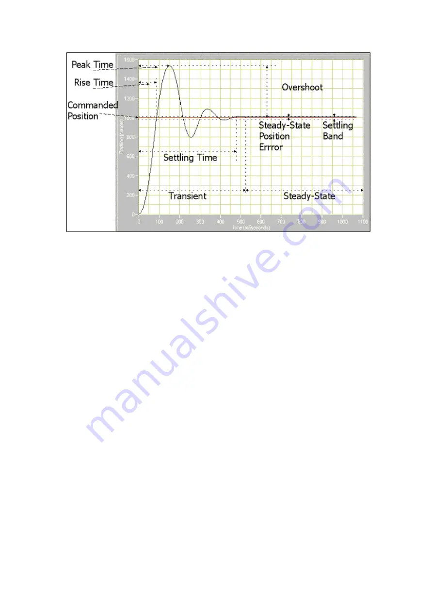
Settling Time—the time required by the response curve to reach and stay within a 
range that is approximately the final value of size specified by the absolute percentage 
of the final value (2% to 5%). 
 
Rise Time—the time required by the response to rise from 10% to 90% of its final 
value; the faster the response time of the system, the faster the rise time. 
 
Peak Time—the time required for a response to reach the first peak of the overshoot. 
 
Maximum Overshoot—the maximum peak value of the response curve measured 
from the desired position. The maximum overshoot directly indicates the relative 
stability of the system. 
 
Commanded Position—the desired position (or rotation speed). In this case, the 
commanded value is 1,000. For the Zeus motor controller this will be the value in Hz 
for 33.33 rpm or 45 rpm. 
 
Steady-State Position Error—the error that occurs when the system is at rest. 
 
Settling Band—the area the position must be within in order to determine settling 
time. 

3.4.1


Analysing step response plots 

This section provides definitions and sample diagrams of the six most common 
response types. 
An unstable system, shown below, produces an oscillatory, exponentially diverging 
step response. This kind of system never settles down; in fact, the oscillations tend to 
worsen over time.  

Summary of Contents for Zeus

Page 1: ...Zeus Turntable Motor Speed Controller Tachometer...

Page 2: ...tive Speed Control PID 12 2 5 1 Turntable PID values 12 2 5 2 Final installation note 13 3 Configuration menus and parameters 14 3 1 1 Setup Menu item entry 14 3 1 2 System Parameters 14 3 1 3 Motor P...

Page 3: ...atter rotation speed and using the PID algorithm adjustment of the AC signals fed to the motor is possible The feedback loop created by the sensor and PID result in accurate speed control and low WOW...

Page 4: ...itch is a standby switch The board may be configured to go into a low power sleep state after a period of inactivity The procedure for installation is in two parts Basic installation and adaptive PID...

Page 5: ...lexible cable attach to the black connector marked LINN PSW1 with the copper contacts uppermost If using the supplied switch remove the existing square LINN switch and replace with the square switch P...

Page 6: ...uld get you through the basic testing for the board To configure the board for basic testing use the PIDTuning application or a serial console application set to 9600 N 8 1 Interaction with the contro...

Page 7: ...question For example Enter 33 3 rpm frequency Hz 45 65 50 0 The question will be followed by the units the range of acceptable values in between the brackets 45 65 and finally the current value 50 0 E...

Page 8: ...he IR sensor lightly Connect the other end of the 4 way FFC cable to connector P3 on the underside of the motor controller PCB silver contacts towards the PCB Position the IR sensor diodes to the outs...

Page 9: ...gered Hand rotate the platter and adjust the position the speed box so that each time the marker passes the trigger message is displayed Also brief flash from the IR sensor registration indicator LED...

Page 10: ...ral bearing hole or other available access point However ensure there are no sharp edges to damage the insulation of the FFC cable Often the bearing bolt heads have sharp edges so endure the FFC cable...

Page 11: ......

Page 12: ...variables and step through the questions setting values for Kp Ki and Kd Quit out to main menu and write the changes to EEPROM using option 6 You may find the turntable takes a little longer to reach...

Page 13: ...slight adjustment of phase angles you can significantly reduce motor vibration and hence audible noise Some of the parameters require a re boot of the controller to take effect remember to write to th...

Page 14: ...value Enter 33 3 rpm frequency Hz The frequency that needs to be supplied to the motor to achieve 33 3 rpm rotation Hz 30 65 50 Enter 45 rpm frequency Hz The frequency that needs to be supplied to th...

Page 15: ...e label Y N N Automatically start platter on application of power The board can automatically start the platter on the application of power rather than having to press a start switch Y N N Crystal tri...

Page 16: ...us motors 85v rms is a good starting point Slight adjustment of phase voltages can reduce motor vibration Start with the defaults and adjust on test If you can hold the motor in your hand this is the...

Page 17: ...333 60 0 55555 0 1 0 66666 Debug PID to Serial Monitor Displays setpoint output feedback values to the serial console When adjusting the PID values using the PIDTuning app this parameter will be set t...

Page 18: ...on of restoring force proportional to the rate of change derivative of position error This force is much like viscous damping in a damped spring and mass mechanical system a shock absorber for example...

Page 19: ...in Use Step Response to determine the relative stability of the system A system is considered stable if the actual value is finite when the commanded value is finite In other words a system is stable...

Page 20: ...e maximum overshoot directly indicates the relative stability of the system Commanded Position the desired position or rotation speed In this case the commanded value is 1 000 For the Zeus motor contr...

Page 21: ...ed system is characterized by a large overshoot a long settling time and short peak and rise times A critically damped system response provides a balanced medium between over and under damping This ty...

Page 22: ...ance graph for observing small response changes Perform the following steps to tune your PID control system You are aiming for a critically damped response 1 Set all three PID parameters Kp Kd and Ki...

Page 23: ...t 1 50 of Kd this will mean that the response will no longer oscillate but will quickly dampen to a steady state value Try to eliminate any peaks You may need to enable the Auto Zoom feature to see th...

Page 24: ...alues by small amounts to achieve the fastest response with minimal overshoot and correction Monitoring fluctuations in the WOW value on the serial monitor is a good indicator Go back to your recorded...

Page 25: ...reases the slope of the initial rise to the commanded position As you increase Kp you approach the commanded position faster and thus overshoot by a greater amount Kd reduces the oscillations over a p...

Page 26: ...master file CH34x_Install_V1 3 zip If you do not have a serial monitor program use the one build into the Arduino IDE Follow the instructions at this link https www arduino cc en Guide MacOSX toc1 Onc...

Page 27: ......

Page 28: ...al switch on 20mA steady state at 230V Replacement Fuse T500mA 250v Dimensions 20 x 165 x 100mm HxWxD Motor Output drive voltage 12v to 110v AC Motor Output drive current 20mA Frequency resolution 0 0...

Reviews: