10
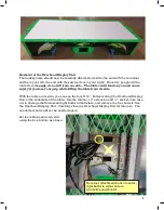
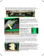
The Secondary Box contains four overhead tubes (two male, two female) and two U-
shaped Legs. Slide the U-shaped legs under the central opening, opposing each other in
this manner as shown in the photo below, with the leg leveler openings facing up.
Note in the photo detail each leg has THREE
mounting holes, and the side of the table has
THREE corresponding holes. Each leg also has a
Wiring Access Hole corresponding to the square
hole in the cabinet.
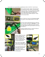
At this point in the assembly process, use
only
the
lowest hole in the table and the lowest hole in the
leg. This is the pivot point for the legs.
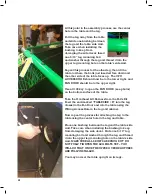
While pulling the leg away
from the table side
,
carefully slide one bushing
between the leg and the
table side wall. Insert one
5/16” leg mounting bolt and
washer through the leg and thread it into the
lowest leg mounting hole on the table’s side wall.
Pressure from the leg will hold the bearing tightly to the table’s side wall, so take care
when moving the table or adjusting the leg position to avoid damage to the side decal.
Turn the bolt by hand two or three turns to secure the leg but AGAIN DO NOT FULLY
TIGHTEN THE BOLT. Repeat the process with the same holes on the opposite side of this
leg. Then attach the table’s right leg in the same manner, remaining careful of the side
wall decal, and hand tightening the bolts 2 or 3 turns.
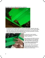
Once both legs have been attached at all four
points and may fully hand tighten all four leg bolts
but DO NOT FULLY TIGHTEN THEM UNTIL THE
OVERHEAD HAS BEEN INSTALLED, have two
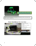
people lift the table back onto its side: coin door
end to the left, service access door end to the
right. CPU ACCESS DOOR to the upper left, FAN
DOOR to the lower left.
CPU
Door
Fan
Door


