background image

VALLEY FORGE & BOLT MANUFACTURING COMPANY

Phone: (602) 269 - 5748

4410 W. Jefferson St. 


Phoenix, AZ 85043 


USA

Fax:

(602) 269 - 7851

SPC4

TM

 SYSTEM 

 MODEL 600A 

 USER'S MANUAL

Rev. 1.1

-  Page 13 of 27  -

-.

9

.-

 - “

RECEIVE DATA

” BUTTON


Downloads  the  contents  of  the  HHU’s  memory  to  a  file  on  your  PC.  The  path  chosen  in  the  “

Saved

Data Destination Folder

” box gives the exact location of this file.

The data files can be opened in Microsoft Excel (for *.xls) or Notepad (for *.txt).
The naming convention of each file is “

Bolt Data

[space]

DATE

[space]

TIME.extension

”.

The  “

DATE

”  field  is  in  MM-DD-YY  format,  and  “

TIME

”  field  is  in  HH-MM-SS  “military”  format

(00:00:00 to 23:59:59, no AM/PM).
For  example,  one received  file  could  be  named  “

Bolt  Data  06-07-09  12-55-18.xls

”,  which  means  the

file was downloaded June 7

th

 2009 at 12:55:18. You might not be able to see the extension  “

.xls

”  (or

.txt

”) if your PC is not set to always show file extensions.

-

10

-

 - PROGRESS BAR


This progress bar shows the progress of the current operation.

-

11

-

 - DATA LOGGER STATUS


This box shows the status of the HHU. The messages displayed here are self-explanatory:
-


Disconnected or OFF

” - link to HHU could not be established;

-


Connected

” - link to HHU OK, user can begin normal operation of the program;

-


Data Transfer in Progress

” - data is transferred from/to the HHU;

-


Writing to Clock

” - HHU's clock is synchronized with the PC's clock;

-


Writing to Timer

” - the settings are downloaded to HHU's idle timer;

-


Re-Formatting Memory

” - the memory is initialized with the custom parameters;

-


Erasing Memory

” - the memory's contents are erased.

1.3.4 USB Cable (UC)

Figure 1.3.6 – USB Cable - Connectors (UC)

..

1

..

- DATA +

..

2

..

- NC (Not Connected)

..

3

..

- DATA -

..

4

..

- VUSB (+ 5V)

..

5

..

- GND (Ground)

..

6

..

- NC (Not Connected)

Summary of Contents for SPC4 600A

Page 1: ...anual SPC4TM Model 600A Electronic Load Data Logger System Firmware Version 1 50 VALLEY FORGE BOLT MANUFACTURING COMPANY 4410 W Jefferson St Phoenix AZ 85043 USA Phone 602 269 5748 Fax 602 269 7851 E mail sales vfbolts com ...

Page 2: ...GHTENING EQUIPMENT FOR SAFETY REASONS NEVER PLACE ANY PART OF YOUR BODY ESPECIALLY YOUR HEAD DIRECTLY IN LINE WITH THE FASTENER ELECTRICITY CAN CAUSE SEVERE INJURIES OR EVEN DEATH SOMETIMES EVEN WITH RELATIVELY LOW VOLTAGES OR CURRENTS THEREFORE IT IS VITALLY IMPORTANT THAT ANY ELECTRONIC INSTRUMENTS SUCH AS THIS SYSTEM BE FULLY UNDERSTOOD BEFORE USE PLEASE DO NOT USE THIS SYSTEM OR ANY OTHER PIEC...

Page 3: ... Operation and Measurement 14 2 1 Warning 15 2 2 Precautions 15 2 3 ABT DAQ Software Installation 16 2 4 Hand held Unit HHU Setup 19 2 5 System Calibration Check 20 2 6 Low Battery Indication and Under voltage Lockout 20 2 7 Checking the Tightness of a Joint 21 2 8 Recording Data in the Field 21 2 9 Downloading Recorded Data to a PC 22 3 0 SPC4TM Model 600A Electronic Load Data Logger System Speci...

Page 4: ...clean for accurate measurement of load see Paragraph 4 0 for recommended cleaning procedures To this end all of the SPC4TM load indicating fasteners have been shipped with plastic caps installed to protect the datum disk surface These protective caps should always remain on the datum disks and only be removed to install the electronic displacement transducer for measuring load After measuring load...

Page 5: ... 27 1 3 Description of the SPC4TM Model 600A Electronic Load Data Logger System 1 3 1 Hand held Unit HHU Figure 1 3 1 Hand held Unit Front View 1 DISPLACEMENT SENSOR CABLE 2 LCD LIQUID CRYSTAL DISPLAY 3 BACKLIGHT BUTTON 4 UP NEXT BUTTON 5 DOWN PREVIOUS BUTTON 6 CLEAR BUTTON 7 ENTER BUTTON 8 BOLT BUTTON 9 USB CONNECTOR 10 LOCATION BUTTON 11 NUMERICAL KEYPAD 12 ON OFF BUTTON ...

Page 6: ...410 W Jefferson St Phoenix AZ 85043 USA Fax 602 269 7851 SPC4TM SYSTEM MODEL 600A USER S MANUAL Rev 1 1 Page 6 of 27 Figure 1 3 2 Hand held Unit Rear View 13 CASE SCREWS x4 14 BATTERY COMPARTMENT DOOR 15 PROTECTION BUMPERS x2 16 BATTERY TAB 17 BATTERY DOOR LATCH ...

Page 7: ...Decrements the bolt number goes back to the previous bolt Can also be used together with the BOLT button or LOCATION button 6 CLEAR BUTTON When pressed and held in for more than 3 seconds resets the HHU When pressed only momentarily a press followed by a release clears cancels various input actions from the keypad 7 ENTER BUTTON When pressed and held in for more than 3 seconds saves the displayed ...

Page 8: ...or of the HHU for calibration purposes 14 BATTERY COMPARTMENT DOOR Permits the access to the battery compartment to replace the batteries The HHU uses six 6 AA size alkaline batteries It is strongly recommended to replace all six batteries at the same time 15 PROTECTION BUMPERS x2 Protect the USB connector from mechanical damage 16 BATTERY TAB Insulating tab inserted at the factory to guarantee th...

Page 9: ...urther divided between a number of locations and bolts For example let s suppose we want to record data from a mill having 5 flanges with 20 bolts per flange Every flange should be assigned to a location number 1 through 5 and every bolt from any flange will be assigned a bolt number 1 through 20 for a total of 100 bolts Using the ABT DAQ software set these numbers of locations and bolts In the fi...

Page 10: ...open the data transfer software the shortcut called ABT DAQ on the Web will open a browser window to our web site the shortcut called Uninstall ABT DAQ will uninstall the ABT DAQ software your previously saved files containing bolt data will NOT be deleted 2 SHORTCUTS ON THE DESKTOP After installation for your convenience the setup program created one or two shortcuts on your desktop The shortcut ...

Page 11: ...ts contents will be left on your PC preserving your data files The exact location of this folder will vary with the WindowsTM version you are running for Windows 98 and Me this location will be C Windows All Users Documents SPC 4 Bolt Data for Windows 2000 and XP this location will be C Documents and Settings All Users Shared Documents SPC 4 Bolt Data for Windows Vista this location will be C User...

Page 12: ...otal records 5 SET CLOCK BUTTON This button synchronizes the Real Time Clock RTC of the HHU with the clock of your computer the date time information of your computer will be sent to the HHU Please make sure the time and the date of your computer are correct before using this button The HHU will use this information when storing data so your records accuracy will be directly dependent of these set...

Page 13: ... the file was downloaded June 7th 2009 at 12 55 18 You might not be able to see the extension xls or txt if your PC is not set to always show file extensions 10 PROGRESS BAR This progress bar shows the progress of the current operation 11 DATA LOGGER STATUS This box shows the status of the HHU The messages displayed here are self explanatory Disconnected or OFF link to HHU could not be established...

Page 14: ... mating between the corresponding connectors see Figure 1 3 7 CPC Features 1 3 5 Calibration Gage CG Figure 1 3 8 Calibration Gage CG The supplied calibration gage see Figure 1 3 8 Calibration Gage CG is used to check the calibration of the hand held unit When the probe is attached to the end marked 0 the 4th line of the HHU s display should read Load 0 or between 5 and 5 When the probe is attache...

Page 15: ... shown in Figure 2 2 1 A While the probe is pushed against the datum disk for engagement slide the exterior sleeve of the transducer towards the fastener until it locks the probe on the datum disk of the fastener To disengage grip the probe in a similar manner and simply slide the sleeve in the opposite direction It is essential to provide a path for the cable and the cable grip to move freely wit...

Page 16: ...ydrocarbons to clean the instruments as damage may occur to the plastic cases If cleaning is necessary use only a mild solution of warm water and detergent 10 Do not attempt to repair the hand held unit or the displacement transducer These units contain no user serviceable parts inside the enclosures 2 3 ABT DAQ Software Installation Insert the ABT DAQ CD in the CD DVD drive of your PC After a sho...

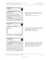
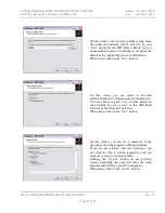
Page 17: ... the I accept the agreement box When ready click on the Next button This screen will show the changes updates and bug fixes made to different versions of the ABT DAQ software the revision history When ready click on the Next button On this screen you can select another installation path for the ABT DAQ software but it is recommended to leave it unchanged accepting the default value might help in c...

Page 18: ...On this screen you can select or de select additional tasks the setup program should perform You can choose to have a set of icons placed on your desktop for easy access to the ABT DAQ software or the future bolt data files When ready click on the Next button On this screen you can see a summary of the operations the setup program will be performing If you are not satisfied with your selections yo...

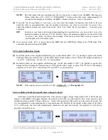
Page 19: ...ct the HHU to your PC using the supplied USB cable 2 Start ABT DAQ Data Transfer Program using the shortcuts created by the setup program and then press and release the ON OFF button on the HHU 3 After power up the line 4 on the HHU s display will show USB meaning the USB interface is connected Also the Data Logger Status of ABT DAQ window will read Connected NOTE If the HHU s display shows Change...

Page 20: ...nd exit ABT DAQ Remove the USB cable This concludes the initial setup of the HHU 2 5 System Calibration Check 1 Install the probe on the supplied calibration gage on the end marked 0 by pushing it against the datum disk and sliding the exterior sleeve of the probe until it locks in place The 4th line of the display should read Load 0 or between 5 and 5 as shown below 2 Install the probe on the sup...

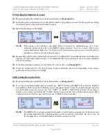
Page 21: ...ened joint it is recommended that three readings be taken to assure uniformity of the load readings 5 If the three percentage readings are not within 5 of each other see Paragraph 4 3 6 Using the calibration curve for the bolt being checked determine the load corresponding to the average percentage reading obtained in step 4 2 8 Recording Data in the Field 1 Begin by checking the calibration of th...

Page 22: ...ven by the location and bolt numbers shown on the LCD place the probe on the bolt you want to measure Press and hold the ENTER button until the display shows Recording Release the ENTER button The bolt number shown on the LCD will automatically advance to the next available bolt number ENTER NOTE If for some reason you are not satisfied with the recorded value press the DOWN PREVIOUS button to sel...

Page 23: ...fter you have verified your saved data double checked you have the file containing the correct data you can click on the Erase Memory button to clear the memory of the HHU 7 You can now click Exit to power down the HHU and exit ABT DAQ Remove the USB cable 3 0 SPC4TM Model 600A Electronic Load Data Logger System Specifications 3 1 Electrical Specifications Power Supply 6 alkaline batteries AA size...

Page 24: ...of wiping with a lint free dry cotton cloth followed by forced moisture free air cleaning An example of a clean and dirty probe face is shown in Figure 4 3 1 The following cleaning recommendations are made in the event that incidental soiling of the datum disk surface does occur 1 In most cases light soiling of the datum disk surface such as moisture dust dirt oil metal chips etc can be cleaned by...

Page 25: ...led above and eliminate the need to unload the fastener HANDLE THE ELECTRONIC INSTRUMENTS WITH CARE AND KEEP PROTECTIVE CAPS ON THE FASTENER DATUM DISKS AT ALL TIMES Valley Forge and Bolt Manufacturing Company assumes no responsibility for inaccurate loading or failure of SPC4TM load indicating fasteners as a result of damage to the measuring instruments caused by improper handling or as a result ...

Page 26: ...aces In most of the cases they will render the probe inoperable And in other cases may result in erroneous consistent readings with a zero offset For example when using the zero datum disk gage a reading of 20 will be displayed instead of 0 and 120 instead of 100 when using the 100 datum disk gage The SPC4TM System is designed to be accurate reliable and easy to use However it is possible that you...

Page 27: ...VALLEY FORGE BOLT MANUFACTURING COMPANY Phone 602 269 5748 4410 W Jefferson St Phoenix AZ 85043 USA Fax 602 269 7851 SPC4TM SYSTEM MODEL 600A USER S MANUAL Rev 1 1 Page 27 of 27 NOTES ...

Reviews: