3
GEAR MOVEMENT
ASSEMBLY
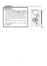
PLUNGER ASSEMBLY
1. Slide the
Plunger Seal
onto the
Plunger (figure 1)
2. Assemble the
Pressure Release Valve Kit
onto the
Plunger
. From the top of the Plunger, place the Washer
onto the Valve Hole, then insert the Screw through the
Washer and into the Valve Hole. From the underside of
the Plunger, place the Spring onto the end of the Screw,
then place the Valve Cap onto the end of the Screw and
twist to secure.
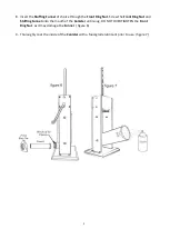
3. Screw the Plunger Bolt onto the Plunger Shaft (figure 2).
4. Place the assembled
Plunger
onto the end of the
Plunger
Shaft (figure 3).
Fast Gear Shaft
With the
Handle
attached, turn
clockwise to raise the
Plunger
;
counter-clockwise to lower the
Plunger
Slow Gear Shaft
With the
Handle
attached, turn
counter-clockwise to raise the
Plunger
;
clockwise to lower the
Plunger
Summary of Contents for 1A-SS710
Page 14: ...2 DIAGRAMME...


