Correcting Malfunctions
7-8
Force EZ-C Series Service Manual
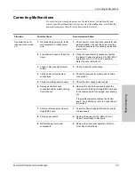
Generator is on and
accessory is activated,
but generator does not
deliver output -
continued
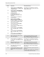
10.
High voltage power supply
malfunction (high voltage is not
present during activation)
10.
If high voltage is not present during activation
at TP20 on the Power Supply RF/Board,
troubleshoot the high voltage power supply as
described below:
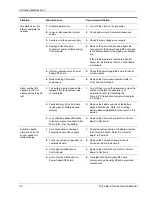
Check the voltages after bridge rectifier CR80
and line filter capacitors at TP10, TP13, and
TP14.
Check switching transistors (Q2, Q4, Q5, and
Q7) for failure (typically fail shorted) at TP7,
TP11, TP18, and TP19 to respective drain and
source pins.
Check high voltage rectifiers CR17, CR22,
CR23, CR36.
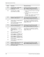
Troubleshoot the pulse-width modulator circuit
(U3 and surrounding components).
Check SYS_ECON circuit from TP3 to U3.
Perform further detailed component
troubleshooting as needed.
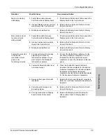
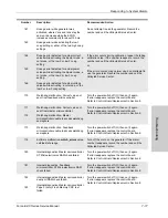
11.
RF output stage malfunction (high
voltage is present during
activation)
11.
If high voltage is present during activation at
TP20 on the Power Supply RF/Board,
troubleshoot the generator as described
below:
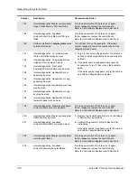
On the Power Supply/RF board, verify T_ON\
pulses during activation at U22 (TP33).
If pulses are not present at TP33, replace the
Control board. Refer to
Control Board
in
Section 8.
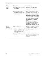
If pulses are present at TP33, but are not
present after U22, replace U22.
On the right heat sink, check the power
MOSFET at J13 for failure (typically fail
shorted).
Check all output relays to verify that they are
toggling during activation. The problem could
be on the Control board at the relay driver
(U16) or K10, K11, K12, K13, or K14.
Perform further detailed component
troubleshooting as needed. Check for shorting
of the output tuning inductors (L2 and L3) and
failure of the output tuning capacitors C143,
C154, C159, C165, C166, etc.
Situation
Possible Cause
Recommended Action


