background image

3-8

SurgiStat II Service Manual

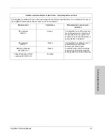
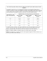
Guidance and manufacturer's declaration - electromagnetic immunity

The SurgiStat II is intended for use in the electromagnetic environment specified below. The customer or the user of 
the SurgiStat II should assure that it is used in such an environment.

Immunity test

IEC 60601 test 

level

Compliance level

Electromagnetic environment - 

guidance

Electrostatic discharge 

(ESD)

IEC 61000-4-2

+/-6 kV contact

+/-8 kV air

+/-6 kV contact

+/-8 kV air

Floors should be wood, concrete or 
ceramic tile. If floors are covered with 
synthetic material, the relative humidity 
should be at least 30%.

Electrical fast transient/

burst IEC 61000-4-4

+/-2 kV for power 

supply lines

+/-1 kV for input/

output lines

+/-2 kV for power 

supply lines

+/-1 kV for input/

output lines

Mains power quality should be that of a 
typical commercial or hospital environment.

Surge

IEC 61000-4-5

+/-1 kV differential 

mode

+/-2 kV common 

mode

+/-1 kV differential 

mode

+/-2 kV common 

mode

Mains power quality should be that of a 
typical commercial or hospital environment.

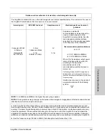
Voltage dips, short 

interruptions and voltage 

variations on power supply 

input lines

IEC 61000-4-11

<5% Ut              

(>95% dip in Ut)       

for 0,5 cycle

40% Ut              

(>60% dip in Ut)       

for 5 cycles

70% Ut              

(>30% dip in Ut)       

for 25 cycles

<5% Ut              

(>95% dip in Ut)       

for 5 sec 

<5% Ut              

(>95% dip in Ut)       

for 0,5 cycle

40% Ut              

(>60% dip in Ut)       

for 5 cycles

70% Ut              

(>30% dip in Ut)       

for 25 cycles

<5% Ut              

(>95% dip in Ut)       

for 5 sec 

Mains power quality should be that of a 
typical commercial or hospital environment. 
If the user of the SurgiStat II requires 
continued operation during power mains 
interruptions, it is recommended that the 
SurgiStat II be powered from an 
uninterruptible power supply or a battery.

Power frequency (50/60 

Hz) magnetic field

IEC 61000-4-8

3 A/m

3 A/m

Power frequency magnetic fields should be 
at levels characteristic of a typical location 
in a typical commercial or hospital 
environment.

NOTE

: Ut is the a.c. mains voltage prior to the application of the test level.

Summary of Contents for SurgiStat II

Page 1: ...Service Manual SurgiStat II Electrosurgical Generator ...

Page 2: ...fect factory repairs Please refer to Section 8 Repair Policies and Procedures for what is covered how long and how to obtain a Return Authorization Number Equipment covered in this manual SurgiStat II Electrosurgical Generator 120 VAC Model Surg II 20 SurgiStat II Electrosurgical Generator 240 VAC Model Surg II 8 SurgiStat II Electrosurgical Generator 100 VAC Model Surg II J Valleylab Part Number ...

Page 3: ... SurgiStat II electrosurgical generator please refer to the User s Guide for standard operating precautions Applicable Safety Standards CSA C22 2 NO 601 1 M90 UL60601 1 IEC 60601 2 2 1998 90 Class 1 Equipment Type CF CENELEC EN 60601 1 2 FCC Part 15 Class A IEC 60601 1 2nd Edition 1988 Conventions Used in this Guide Indicates an operating tip or maintenance suggestion Warning Indicates a potential...

Page 4: ...2 6 Power Switch and Receptacles 2 7 Rear Panel 2 8 Symbols on the Front Panel 2 9 Section 3 Technical Specifications Performance Characteristics 3 2 Duty Cycle 3 2 Dimensions and Weight 3 2 Operating Parameters 3 3 Transport and Storage 3 3 Audio Volume 3 3 Patient Return Electrode Sensing 3 4 Low Frequency 50 60 Hz Leakage Current 3 5 High Frequency RF Leakage Current 3 5 Standards and IEC Class...

Page 5: ...ration Inspecting the Generator and Accessories 5 2 Service Personnel Safety 5 2 Installation and Placement 5 3 Functional Operational Checks 5 3 How to Set Up and Start the SurgiStat II Unit 5 3 How to Check the Patient Return Electrode Alarm Function 5 4 How to Check the Bipolar Mode with Footswitch 5 4 How to Check the Monopolar Mode with Footswitch 5 4 How to Check the Monopolar Mode with Hand...

Page 6: ...nty Section A Board Drawings and Schematics Main Board A 3 Power Supply A 4 RF Amplifier Circuit A 5 Request Sense Circuit Hand A A 6 Request Sense Circuit Hand B A 7 Request Sense Circuit Foot A A 8 Request Sense Circuit Foot B A 9 Display Board A 10 Display Logic A 11 Monopolar Select Circuit A 12 Main Printed Circuit Board A 13 Display Printed Circuit Boards A 14 Relay Printed Circuit Board A 1...

Page 7: ...following information Key features Components and accessories Safety Caution Read all warnings cautions and instructions provided with this generator before using Read the instructions warnings and cautions provided with electrosurgical accessories before using Specific instructions are not included in this manual ...

Page 8: ...Up to 30 W of Bipolar 200 Ω Two Levels of Coagulation Desiccation and Fulguration Desiccation provides precise control of bleeding in localized areas Fulguration provides greater control of bleeding in highly vascular tissue over broader tissue surface areas Return Electrode Monitoring System The unit incorporates a return electrode contact quality monitoring system RECQMS This system determines t...

Page 9: ...he Generator Before testing this generator it is important that you read understand and follow the instructions supplied with it Also be familiar with any other equipment used to install and test the generator General Warnings Cautions and Notices Standard Front Panel Connectors These connectors accept the latest monopolar and bipolar instruments Self Diagnostics These diagnostics continually moni...

Page 10: ...al equalization grounding connector with an equipotential cable Connect the power cord to a wall receptacle having the correct voltage Otherwise product damage may result Warning Electric Shock Hazard Do not connect wet accessories to the generator Electric Shock Hazard Ensure that all accessories and adapters are correctly connected and that no metal is exposed Caution Accessories must be connect...

Page 11: ...power cord to a properly grounded receptacle Do not use power plug adapters Do not connect a wet power cord to the generator or to the wall receptacle Always turn off and unplug the generator before cleaning Do not touch any exposed wiring or conductive surfaces while the generator is disassembled and energized Never wear a grounding strap when working on an energized generator When taking trouble...

Page 12: ...rovided with this generator before testing Notice There are no internal user serviceable parts For repairs return the generator to Valleylab Notice Do not clean the generator with abrasive cleaning or disinfectant compounds solvents or other materials that could scratch the panels or damage the generator ...

Page 13: ...SECTION 2 SurgiStat II Service Manual 2 1 2Controls Indicators and Receptacles This section describes the front and rear panels including all controls indicators receptacles the fuse drawer and ports ...

Page 14: ...2 2 SurgiStat II Service Manual Front Panel Figure 2 1 Layout of controls indicators and receptacles on the front panel ...

Page 15: ...g from 1 to 120 watts in one watt increments at the rated load During operation the numeral output of the display gives the surgeon an indication of available generator power Visual LED Indictors Mode LEDs indicate the mode setting The YELLOW indicators and controls indicate cutting and blending operations A yellow field LED indicates that either a Pure Cut or Blend mode is activated The BLUE indi...

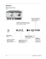
Page 16: ...Blend Indicator Illuminates when Blend mode is selected Cut and Blend Power Display watts Indicates the power set for the Pure Cut or Blend mode Cut and Blend Activation Indicator Illuminates when either Pure Cut or Blend mode is activated Cut and Blend Power Control Dial Increases or decreases the Cut or Blend power output in increments of one watt Cut Indicator Illuminates when Pure Cut mode is ...

Page 17: ...ates the power set for any Coag or Bipolar mode Coag and Bipolar Activation Indicator Illuminates when Desiccate Fulgurate or Bipolar modes are activated Coag and Bipolar Power Control Dial Increases or decreases the Coag or Bipolar power output in increments of one watt Fulgurate Indicator Illuminates when Fulgurate mode is selected Fulgurate Selector When pressed selects the Fulgurate mode Desic...

Page 18: ...t control is selected Power Indicator Illuminates when the unit is on Single Plate Patient Return Electrode Indicator Illuminates when the system detects a single plate Monopolar Footswitch Control Indicator and Symbol Illuminates when monopolar foot control is selected Patient Return Electrode Alarm Indicator Illuminates when the system detects a patient return electrode alarm condition Split Pla...

Page 19: ...ccepts standard three pin handpieces Connect handswitching accessories Bipolar Receptacle Accepts standard cables for bipolar handpieces Power On Off Switch Turns the unit on or off Monopolar Footswitching Receptacle Accepts cables or adapters equipped with standard Bovie 12 active plugs Connect footswitching accessories Patient Return Electrode Receptacle Accepts a standard patient return electro...

Page 20: ...e volume rotate the knob clockwise Footswitch Receptacle Accepts the E6008 or E6008B monopolar footswitch Use the monopolar footswitch for both monopolar and bipolar activation Use only a Valleylab monopolar footswitch with a SurgiStat II generator Use of an incompatible footswith may cause unexpected output Serial Number Label Specifies the unit model number serial number nominal line voltage fre...

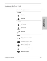
Page 21: ...Panel Symbols Description Cut Controls Cut mode Blend mode Coag Controls Desiccate mode Fulgurate mode Bipolar mode Indicators Single plate patient return electrode Split plate patient return electrode Monopolar footswitch control Footswitch on the selector button Bipolar footswitch control ...

Page 22: ... and Handpiece Connectors Read instructions before use Type CF equipment Patient return electrode RF isolated patient connections are isolated from earth at high frequency Caution high voltage Monopolar output Bipolar output Symbols Description F ...

Page 23: ...ptacles SurgiStat II Service Manual 2 11 Symbols on the Rear Panel Symbols Description Equipotential ground stud Nonionizing radiation Volume control Danger Explosion risk if used with flammable anesthetics Monopolar footswitch Read instructions before use ...

Page 24: ...2 12 SurgiStat II Service Manual ...

Page 25: ...ual 3 1 3Technical Specifications All specifications are nominal and subject to change without notice A specification referred to as typical is within 20 of a stated value at room temperature 25 C 77 F and a nominal input power voltage ...

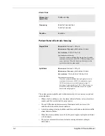
Page 26: ...or calibration 230 V Nominal input power voltage for calibration 100 V Mains line frequency range nominal 50 60 Hz Mains line frequency range nominal 50 60 Hz Mains line frequency range nominal 50 60 Hz Power consumption 360 VA Power consumption 360 VA Power consumption 360 VA Fuses 2 5A Slow Blow Fuses 2 3 15A Slow Blow Fuses 2 5A Slow Blow Notice The internal temperature of the unit is constantl...

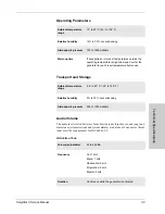
Page 27: ...to 40 C 50 to 104 F Relative humidity 15 to 75 noncondensing Atmospheric pressure 700 to 1060 millibars Warm up time If transported or stored at temperatures outside the operating temperature range allow one hour for the generator to reach room temperature before use Ambient temperature range 34 to 65 C 29 to 149 F Relative humidity 0 to 75 noncondensing Atmospheric pressure 500 to 1060 millibars ...

Page 28: ...ding to IEC 60601 1 Volume not adjustable 70 dBA 5 dBA Frequency 2 kHz for 1 second then 1 kHz for 1 second Duration 4 seconds Single Plate Measurement current 100 µA Measurement frequency 62 5 kHz 2 5 kHz Set resistance 0 Ω to 5 Ω 3 Ω Continuous measurement Once the system establishes the single plate electrode resistance an increase of 20 Ω 5 Ω in resistance will cause an alarm When the alarm co...

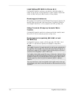
Page 29: ...ive earth conductor Type CF Equipment IEC 60601 1 Defibrillator Proof Enclosure source current ground open 300 µA 90V 110V mains voltage 110V 120V 500 µA 220V 240V mains voltage Source current patient leads all outputs Normal polarity intact ground 10 µA Normal polarity ground open 50 µA Reverse polarity ground open 50 µA Sink current at high line all inputs 50 µA Bipolar RF leakage current 39 mAr...

Page 30: ...ity IEC 60601 1 2 and IEC 60601 2 2 The SurgiStat II generator complies with the appropriate IEC 60601 1 2 and IEC 60601 2 2 specifications regarding electromagnetic compatibility Notice The SurgiStat II should not be used adjacent to or stacked with equipment other than specified in the SurgiStat II User Guide and Service Manual If adjacent or stacked use is necessary the SurgiStat II should be o...

Page 31: ...ment guidance RF emissions CISPR 11 Group 2 The SurgiStat II uses RF energy only for its internal function Therefore its RF emissions are very low and are not likely to cause any interference in nearby electronic equipment RF emissions CISPR 11 Class A The SurgiStat II is suitable for use in all establishments other than domestic and those directly connected to the public low voltage power supply ...

Page 32: ... 5 1 kV differential mode 2 kV common mode 1 kV differential mode 2 kV common mode Mains power quality should be that of a typical commercial or hospital environment Voltage dips short interruptions and voltage variations on power supply input lines IEC 61000 4 11 5 Ut 95 dipinUt for 0 5 cycle 40 Ut 60 dipinUt for 5 cycles 70 Ut 30 dipinUt for 25 cycles 5 Ut 95 dipinUt for 5 sec 5 Ut 95 dipinUt fo...

Page 33: ...strengths from fixed RF transmitters as determined by an electromagnetic site survey should be less than the compliance level in each frequency range Interference may occur in the vicinity of equipment marked with the following symbol NOTE 1 At a 80MHz and 800MHz the higher frequency range applies NOTE 2 These guidelines may not apply in all situations Electromagnetic propagation is affected by ab...

Page 34: ...W Separation distance according to frequency of transmitter m 150 kHz to 80MHz d 1 2 P 80MHz to 800MHz d 1 2 P 800MHz to 2 5GHz d 2 3 P 0 01 0 12 m 0 12 m 0 23 m 0 1 0 38 m 0 38 m 0 73 m 1 1 2 m 1 2 m 2 3 m 10 3 8 m 3 8 m 7 3 m 100 12 m 12 m 23 m For transmitters rated at a maximum output power not listed above the recommended separation distance d in meters m can be estimated using the equation a...

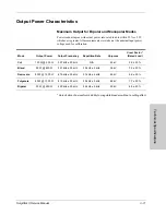
Page 35: ...age used for calibration An indication of a waveform s ability to coagulate bleeders without a cutting effect Mode Output Power Output Frequency Repetition Rate Vp p max Crest Factor Rated Load Cut 120 W 500 Ω 357 kHz 50 kHz N A 2 5 kV 2 9 20 Blend 90 W 800 Ω 357 kHz 50 kHz 30 kHz 5 kHz 3 5 kV 3 3 20 Desiccate 80 W 1000 Ω 475 kHz 50 kHz 57 kHz 5 kHz 4 5 kV 5 5 20 Fulgurate 40 W 1000 Ω 410 kHz 50 k...

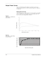
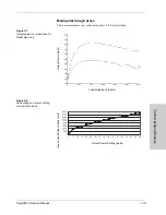
Page 36: ...lar Cut Curves These measurements were taken using short 0 5 meter leads For each output power vs impedance curve the upper curve represents readings taken at full power the lower curve readings taken at half power Figure 3 1 Output power vs impedance for Pure Cut mode Figure 3 2 Peak voltage vs power setting for Pure Cut mode Load Resistance ohms Output Power watts Output Power Setting watts Open...

Page 37: ...enerator settings for Pure Cut mode Figure 3 4 Output power vs impedance for Blend mode 0 10 20 30 40 50 60 70 80 90 100 110 120 130 0 5 10 15 20 25 30 35 40 45 50 55 60 65 70 75 80 85 90 95 100 105 110 115 120 Output Power watts Generator Setting Load Resistance ohms Output Power watts ...

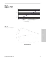
Page 38: ...setting for Blend mode Figure 3 6 Output power vs generator settings for Blend mode Output Power Setting watts Open Circuit Peak Voltage volts 0 10 20 30 40 50 60 70 80 90 100 0 5 10 15 20 25 30 35 40 45 50 55 60 65 70 75 80 85 90 Output Power watts Generator Setting ...

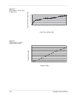
Page 39: ...rves These measurements were taken using short 0 5 meter leads Figure 3 7 Output power vs impedance for Desiccate mode Figure 3 8 Peak voltage vs power setting for Desiccate mode Load Resistance ohms Output Power watts Output Power Setting watts Open Circuit Peak Voltage volts ...

Page 40: ...ower vs generator settings for Desiccate mode Figure 3 10 Output power vs impedance for Fulgurate mode 0 10 20 30 40 50 60 70 80 0 5 10 15 20 25 30 35 40 45 50 55 60 65 70 75 80 Output Power watts Generator Setting Load Resistance ohms Output Power watts ...

Page 41: ... 3 11 Peak voltage vs power setting for Fulgurate mode Figure 3 12 Output power vs generator settings for Fulgurate mode Output Power Setting watts Open Circuit Peak Voltage volts 0 5 10 15 20 25 30 35 40 0 5 10 15 20 25 30 35 40 Output Power watts Generator Setting ...

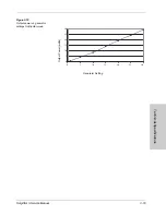
Page 42: ...ual Bipolar Curves Figure 3 13 Output power vs impedance for Bipolar mode Figure 3 14 Peak voltage vs power setting for Bipolar mode Load Resistance ohms Output Power watts Output Power Setting watts Open Circuit Peak Voltage volts ...

Page 43: ...Technical Specifications SurgiStat II Service Manual 3 19 Figure 3 15 Output power vs generator settings for Bipolar mode 0 5 10 15 20 25 30 0 5 10 15 20 25 30 Output Power watts Generator Setting ...

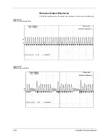
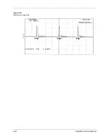
Page 44: ...3 20 SurgiStat II Service Manual Reference Output Waveforms The following figures are the output waveforms as viewed on an oscilloscope Figure 3 16 Pure Cut mode waveform Figure 3 17 Blend mode waveform ...

Page 45: ...Technical Specifications SurgiStat II Service Manual 3 21 Figure 3 18 Desiccation mode waveform Figure 3 19 Fulguration mode waveform ...

Page 46: ...3 22 SurgiStat II Service Manual Figure 3 20 Bipolar mode waveform ...

Page 47: ...TION 4 SurgiStat II Service Manual 4 1 1 Theory Of Operation This section includes the following information Block diagram Functional overview of key circuits System logic Control signal inputs and outputs ...

Page 48: ...the high voltage power supply is 87 VDC 5 V Low Voltage DC Supplies The unit incorporates four regulated low voltage levels to control generator operations They are 15 VDC 12 VDC 8 VDC and 5 VDC The 15 VDC circuit supplies power for all of the request sense circuits the switching of the mode relays and the audio circuit The 12 VDC circuit supplies power for the patient electrode sense module The 8...

Page 49: ... operates at its set operating frequency and presents a sine wave to the level detection circuit The level detection circuit converts the sine wave into a square wave Activation will not occur as long as a square wave is present When a resistance approximately 200 Ω or less is presented to the transformer s secondary winding by a hand control or foot control the sense transformer is essentially sh...

Page 50: ...amplifier incorporating three power MOSFETs and two toroidal step up transformers The digital PWM circuit and the system logic unit generate the initial RF drive pulse When the RF drive pulse turns the power MOSFETs On current flows from the high voltage supply through one of the output transformers depending on which mode the unit is in through the clamping diodes and then through the MOSFETs to ...

Page 51: ... of the unit The system logic uses this digitally controlled signal to provide a precise signal to the RF drive The power setting generated by the user on the front of the unit determines the pulse width When the user sets the power the system logic determines what the pulse width needs to be to deliver the requested output System Logic The control logic uses a field programmable gate array as the...

Page 52: ...ad sense module that informs the system logic that a split plate patient return electrode is attached to the patient When the pad sense module senses the presence of a split patient return electrode a logic 0 0 VDC is sent to the system logic AUD_DRV This is an output signal from the system logic that generates the activation tones for all modes of operation A 1 kHz square wave is generated when t...

Page 53: ...When the cable is damaged not secure or not connected a logic 1 5 VDC is sent to the system logic TEMP_SEN This is an input signal from the temperature sense circuit that informs the system logic if the internal temperature of the unit is above 85 C 185 F If the internal temperature of the unit is below 85 C 185 F a logic 1 5 VDC is sent to the system logic If the internal temperature of the unit ...

Page 54: ...ignal from the foot A request sense circuit foot A refers to the Cut pedal on the footswitch A Colpitts oscillator located on the main board generates this signal When an activation request occurs this oscillator issues a logic 1 5 VDC signal ACT_REQ_FOOT_B This is an input signal from the foot B request sense circuit foot B refers to the Coag pedal on the footswitch A Colpitts oscillator located ...

Page 55: ... Service Manual 5 1 1Generator Operation This section covers the following topics Inspecting the generator and accessories Service personnel safety Installation and placement Functional operational checks Operating the unit ...

Page 56: ...requency and voltage characteristics that match those listed on the back of the unit Fire Hazard Do not use extension cords Caution Do not stack equipment on top of the generator or place the generator on top of electrical equipment These configurations are unstable and or do not allow adequate cooling Provide as much distance as possible between the electrosurgical generator and other electronic ...

Page 57: ... the unit Use only a Valleylab footswitch with the SurgiStat II generator Although other types of footswitches may fit they may not be compatible with this electrosurgical generator Use of an incompatible footswitch may cause unexpected output 4 Do not connect a patient return electrode to the front of the unit at this time 5 Turn on the unit by switching the power switch to the On position 6 The ...

Page 58: ...e Bipolar mode rotate the volume control over the full range to verify that the sound is audible throughout the range 4 Confirm that releasing the Coag pedal or Cut pedal returns the unit to an idle state How to Check the Monopolar Mode with Footswitch 1 Select monopolar foot control by pressing the Footswitch Control Selector until the Monopolar Footswitch Control Indicator illuminates 2 Connect ...

Page 59: ...en select the power setting by rotating the Coag and Bipolar Power Control Dial Bipolar Select the mode of operation for Bipolar coagulation or fulguration then select the bipolar power settings by rotating the Coag and Bipolar Power Control Dial Activate the generator by pressing the appropriate button on the handswitch or footswitch Notice One footswitch can activate either monopolar or bipolar ...

Page 60: ...5 6 SurgiStat II Service Manual ...

Page 61: ...SECTION 6 SurgiStat II Service Manual 6 1 1Maintenance This section includes the following information Cleaning the unit Performing periodic inspection Replacing fuses ...

Page 62: ...hs visually inspect the generator for signs of wear or damage In particular look for any of the following problems Damage to the power cord Damage to the power cable receptacle Obvious damage to the unit Damage to any receptacle Accumulation of lint or debris in or around the unit Warning Electric Shock Hazard Always turn off and unplug the generator before cleaning Caution Do not allow fluids to ...

Page 63: ...l 3 To release the fuse drawer insert a small flathead screwdriver into the slot on the drawer below the power cord receptacle Then slide the drawer out 4 Remove the two fuses and replace them with new fuses with the same values 5 Insert the fuse drawer into the power cable receptacle Use the following fuses Surg II 20 110 120 V Surg II 8 220 240 V Surg II J 90 110 V VAC 250 250 250 Amps 5 0 A 3 1...

Page 64: ...6 4 SurgiStat II Service Manual ...

Page 65: ...SECTION 7 SurgiStat II Service Manual 7 1 1 Troubleshooting This section includes error code descriptions and actions to take to resolve them ...

Page 66: ...ion in this section to perform the following activities Identify and correct the malfunction If the system displayed an error code take the appropriate action s to correct the error condition Inspecting the Generator If the SurgiStat II malfunctions check for obvious conditions that may have caused the problem 1 Check the generator for visible signs of physical damage 2 Verify that all accessory c...

Page 67: ...eceptacle is damaged contact your Valleylab Service Center 7 Check the monopolar handpiece receptacle on the front of the unit for obstruction or damage 8 Insert a handswitching pencil into the monopolar handpiece receptacle on the front of the unit Check for a secure fit If the monopolar handpiece receptacle is damaged contact your Vallylab Service Center 9 Check the monopolar foot controlled rec...

Page 68: ...stuck Handswitch or monopolar footswitch coag pedal may be stuck 1 Turn off then turn on the generator Do not press buttons or accessory activation devices during the self test 2 If the alarm number reappears disconnect all accessories Turn off then turn on the generator again 3 If the problem persists replace the handpiece or footswitch and repeat Step 1 4 If the alarm number reappears record the...

Page 69: ... Turn unit off 2 If error code occurred directly after changing mode of operation turn on the unit and delay activation of the accessories after changing mode of operation 3 If error code occurred directly after changing the power setting during activation turn on the unit and limit the change of power to approximately three watts per second 4 If alarm number reappears upon restarting the unit rec...

Page 70: ...tact your Valleylab Service Center Loose or disconnected internal cables Contact your Valleylab Service Center Faulty power entry module or connections Faulty power switch Generator is on but did not complete the self test Alarm condition exists Check the display for an error code Note the number and refer to error code list Loose or disconnected internal cables Contact your Valleylab Service Cent...

Page 71: ... generator 3 Replace the accessory if it continues to malfunction Display board malfunction Contact your Valleylab Service Center Power set too low Increase the power setting An error condition exists 1 Check the cut and coag displays for an error code number 2 Note the number and refer to the error codes descriptions in this section Main board malfunction Contact your Valleylab Service Center RF ...

Page 72: ...erator is activated Metal to metal sparking Check all connections to the generator patient return electrode and accessories High settings used for fulguration Use lower power settings for fulguration or select the Desiccate mode Electrically inconsistent ground wires in the operating room Verify that all ground wires are as short as possible and go to the same grounded metal If interference contin...

Page 73: ...e does not pass through the vicinity of the heart or the site where the pacemaker is implanted 3 Always monitor patients with pacemakers during surgery and keep a defibrillator available 4 Consult the pacemaker manufacturer or hospital 5 Contact the Cardiology Department for further information when use of electrosurgical appliances is planned on patients with cardiac pacemakers Abnormal neuromusc...

Page 74: ...7 10 SurgiStat II Service Manual ...

Page 75: ...SECTION 8 SurgiStat II Service Manual 8 1 1Repair Policy and Procedures This section contains the following information The manufacturer s responsibility Returning the generator for service ...

Page 76: ...e with the Valleylab instructions for use For warranty information refer to Section 9 Warranty Returning the Generator for Service Before you return the generator call your Valleylab representative for assistance If instructed to send the generator to Valleylab first obtain a Return Authorization Number Then clean the generator and ship it to Valleylab for service Obtain a Return Authorization Num...

Page 77: ...erator is completely dry before you pack it for shipment Package it in its original shipping container If the original shipping container is not available request one when obtaining your Return Authorization Number 3 Ship the generator prepaid to the Valleylab Service Center Service Center For a complete list of service centers worldwide please refer to the Valleylab website http www valleylab com...

Page 78: ...8 4 SurgiStat II Service Manual ...

Page 79: ...Valleylab s factory in a way so as in Valleylab s judgment to affect its stability or reliability or which has been subjected to misuse neglect or accident The warranty periods for Valleylab products are as follows ForceTriad Energy Platform One year from date of shipment Electrosurgical Generators One year from date of shipment RFG 3C Plus Lesion Generator One year from date of shipment LigaSure ...

Page 80: ...the aggregate purchase price for the goods sold by Valleylab to the customer There are no warranties which extend beyond the terms hereof Valleylab disclaims any liability hereunder or elsewhere in connection with the sale of this product for indirect or consequential damages This warranty and the rights and obligations hereunder shall be construed under and governed by the laws of the State of Co...

Page 81: ...II Service Manual A 1 3Board Drawings and Schematics This supplement contains the assembly drawings and schematics for the following printed circuit boards Control board Display board Footswitch board Power Supply RF board ...

Page 82: ...A 2 SurgiStat II Service Manual ...
Reviews: