4-2
SurgiStat II Service Manual
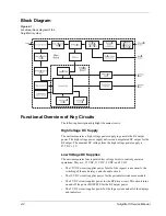
Block Diagram
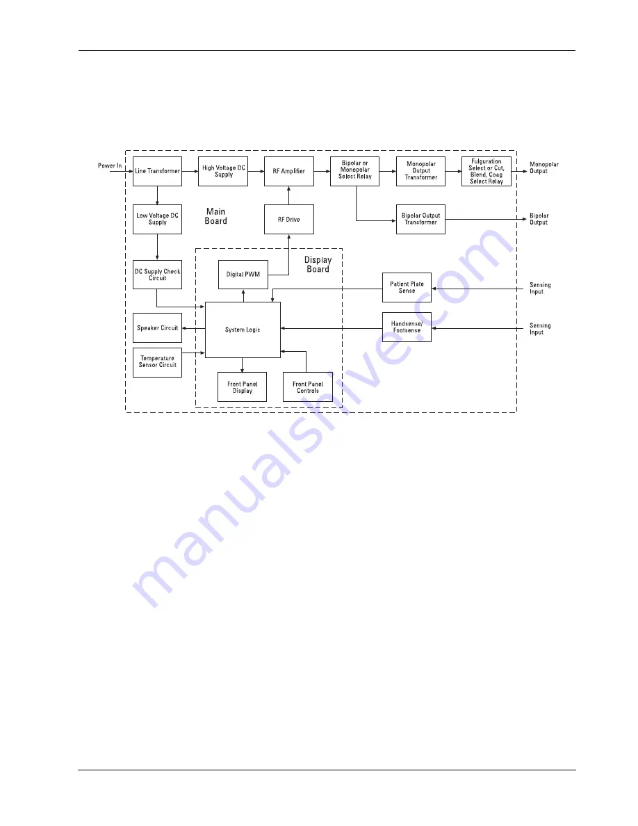
Figure 4-1 .
Functional block diagram of the
SurgiStat II system
Functional Overview of Key Circuits
The following descriptions highlight the main circuits.
High Voltage DC Supply
The unit incorporates a high voltage power supply to generate the RF output
power. The high voltage power supply delivers an unregulated DC output for the
RF output. The nominal DC voltage from the high voltage power supply is
87 VDC ± 5 V.
Low Voltage DC Supplies
The unit incorporates four regulated low voltage levels to control generator
operations. They are: 15 VDC, 12 VDC, 8 VDC, and 5 VDC.
•
The 15 VDC circuit supplies power for all of the request sense circuits, the
switching of the mode relays, and the audio circuit.
•
The 12 VDC circuit supplies power for the patient electrode sense module.
•
The 8 VDC circuit supplies power for the RF drive circuit. This circuit turns
on and off the power MOSFETS for the RF output power.
•
The 5 VDC circuit supplies power for the logic system and all of the displays
and indicators.
Summary of Contents for SurgiStat II
Page 1: ...Service Manual SurgiStat II Electrosurgical Generator ...
Page 24: ...2 12 SurgiStat II Service Manual ...
Page 46: ...3 22 SurgiStat II Service Manual Figure 3 20 Bipolar mode waveform ...
Page 60: ...5 6 SurgiStat II Service Manual ...
Page 64: ...6 4 SurgiStat II Service Manual ...
Page 74: ...7 10 SurgiStat II Service Manual ...

