Theory Of Operation
SurgiStat II Service Manual
4-5
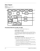
Controls and Indicators
The SurgiStat II uses the following controls and indicators:
•
Membrane switches
These switches switch between modes.
•
Displays
Seven segment displays indicate the output power in watts.
•
Mode indictors
Green LEDs indicate the present mode of the unit.
•
Power control knobs
These mechanical encoders adjust the output power
for each mode.
•
Power switch
A double pole single throw switch snaps into the front bezel.
This switch supplies the AC mains current to the generator.
Digital PWM Circuit
The digital PWM circuit controls the output power of the unit. The system logic
uses this digitally controlled signal to provide a precise signal to the RF drive.
The power setting (generated by the user on the front of the unit) determines the
pulse width.
When the user sets the power, the system logic determines what the pulse width
needs to be to deliver the requested output.
System Logic
The control logic uses a field programmable gate array as the generator “brain.”
This system interprets all inputs and delivers the correct corresponding outputs.
This system controls every operation of the unit.
A system clock circuit, composed of an oscillator, provides the basic operating
frequency of 5 MHz.
The reset circuit provides a single pulse when you turn on the SurgiStat II
generator. This pulse resets the field programmable gate array to ensure proper
operation.
Summary of Contents for SurgiStat II
Page 1: ...Service Manual SurgiStat II Electrosurgical Generator ...
Page 24: ...2 12 SurgiStat II Service Manual ...
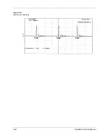
Page 46: ...3 22 SurgiStat II Service Manual Figure 3 20 Bipolar mode waveform ...
Page 60: ...5 6 SurgiStat II Service Manual ...
Page 64: ...6 4 SurgiStat II Service Manual ...
Page 74: ...7 10 SurgiStat II Service Manual ...

