VALLOX 252 M
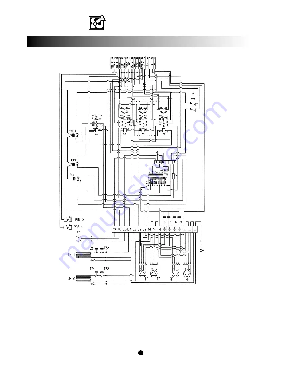
INTERNAL WIRING DIAGRAM VALLOX 252 M
2
18
K4 = Contactor, disconnection of the heating units for heat recovery bypass
S = Service switch (door switch)
LP1 = Preheater 2,500W (optional)
LP2 = Post-heating unit 2,500W (optional)
TZ1 = Overheating pro60oC
TZ2 = Overheating pro95oC (manual reset)
PDS1 = Supply air duct pressure difference switch (optional)
PDS2 = Discharge air duct pressure difference switch (optional)
F1 = Fuse 4A
F2 = Fuse 1.6A
TF = Supply air fan 2x230W
PF = Discharge air fan 2x230W
C = Capacitor 6mF
FG = Damper motor
TR = Transformer 230V 4A/24V 25VA
TS1 = Defrosting thermostat for heat recovery cells + 2oC (adjustable)
TS2 = Thermostat for post-heating unit +15oC...25oC
TS5 = Thermostat for pre4oC (adjustable)
K1 = Contactor max. speed
K2 = Contactor min. speed
K3 = Contactor 1/2 speed


