VALLOX 90 SE
© VALLOX • We reserve the right to make changes without prior notification.
Vallox Oy • Myllykyläntie 9-11 • FI-32200 Loimaa • Tel. +358 10 7732 200 • www.vallox.com
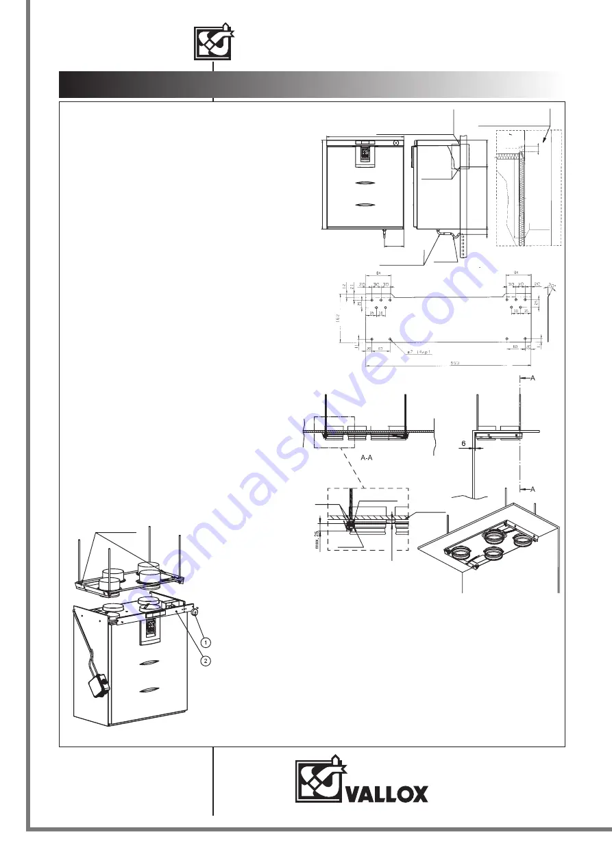
LOCATION OF VALLOX 90 SE
1.09.331E/9.4.2013/PDF
597
68
8
150
40
48
2
206
LOWER EDGE
OF BRACKET
THE LEAD-IN OF ELECTRIC WIRES
CAN BE DONE FROM BOTH SIDES OF
THE UNIT.
Condensing water
outlet and water seal
Cu ø12x1
DURING MOUNTING THE UNIT RISES 10
MM HIGHER THAN THE FINAL HEIGHT.
10
160
Lower edge
of bracket
Installation
VALLOX 90 SE has to be mounted in a place where temperature
does not fall below +10 ºC. Without protective casing, the unit
must be located in a place with no acoustic disturbance: storerooms,
technical rooms etc.
Wall mounting
VALLOX 90 SE is mounted on the wall with a fixing plate as
shown in the adjacent figure.
Wall construction
When fixing the unit, take the wall structure into account. Avoid mounting
the unit on a hollow, echoing dividing wall and on a bedroom wall
because of sound conduction, or prevent sound conduction.
Wall mounting plate
Condensing water
The delivery includes a water seal. With a pipe connected to the water seal,
water condensing from extract air can be led to a floor drain (not straight
to the drain) The pipe must not rise after the water seal. The unit has to be
mounted level with the horizontal in order to ensure that condensing water
can get out of the unit.
Ceiling mounting/ceiling mounting plate
Fastening of ceiling mounting plate to ceiling
The ceiling mounting plate is mounted straight, and it has to be fastened
so that there is a space of circa 6 mm between the back edge of the
ceiling mounting plate and the wall (Figure 1).The ventilation unit
becomes attached to the back wall. Minimum distance between the lower
edge of the ceiling mounting plate and the ceiling of the room is 14 mm.
Wit this distance, there will be a vent of circa 2 mm between the upper
edge of the mounted unit and the ceiling.
The ceiling mounting plate is fixed to the ceiling with M8 thread bars.
When the thread bars have been fastened to the ceiling, first turn the nuts
into the thread bars and lift the ceiling mounting plate in place. Then push
a rubber damper and washer to each thread bar, all the way into the cup
of the plate, and turn the nut. Shorten the lower ends of the thread bars so
that they will be at no more than 25 mm from the lower surface of the
ceiling mounting plate. NOTE! Shortening the thread bars can only be
done before mounting the ceiling mounting plate. The maximum length of
a thread bar from the lower surface of the ceiling is the space between the
lower surface of the ceiling and the lower surface of the ceiling mounting
plate + 25 mm.
Mounting of ventilation unit to ceiling
mounting plate
Before lifting the unit to the ceiling mounting plate, detach
the following items from the unit (Figure 2):
1. Thermostat knob (SC unit)
2. Front panel (leave it hanging from the measurement
hoses)
Put the cables of the connection box into the slot in the
upper part of the side plate and pull the connection box
next to the unit so that the cables remain in the slot. Make
sure that the duct outlets for the unit’s extract air duct and
for the duct coming from the outside to the unit are
equipped with condensing water insulation. Lift the unit in
place to the ceiling mounting plate till both locking wings
lock to the outer edge of the side plate of the unit. Do a
visual check of the tightness of the duct outlets and of the
correct moving of the measurement hoses and electric
cables. Fasten the front panel and the knob of the
thermostat (SC unit) back in place.
Attention!
To prepare for external connections from the
electrical box of the unit, you can fix the
electrical box on the wall beside the unit.
Air flow measurement outlets
The fixed measurement outlets for air flow are
located behind the nameplate of the unit. You
can measure the total pressure of the supply
and extract air ductwork at the measurement
outlets, using a differential pressure instrument.
Pressure readings and the unit’s air volume
tables show volume air flows at various
adjustment positions. The red measurement
hose is on the pressure side and the black hose
on the suction side of the fan.
Figure 1
Nuts
Damper rubber
Lower
surface
of ceiling
Washer
at least 14
wall
ceiling
Locking wing
Figure 2


