background image

© VALLOX • We reserve the right to make changes without prior notification.
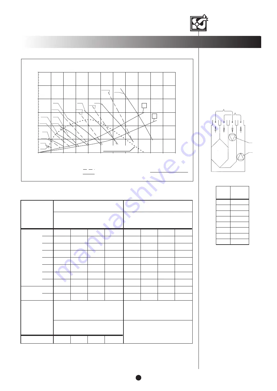
Air volumes

Measuring points after the
connection outlet.
Fan curves indicate the total
pressure available for duct losses.

Extract air

Supply air

S

E

SUPPLY/EXTRACT AIR VOLUMES / VALLOX 90 SE

(10 m

2

:n sound absorption)

Sound power level from the ventilation unit

to supply air ducts by octave band Lw, dB

Medium

frequency

of the octave

band,

Hz

ADJUSTMENT POSITION/AIR FLOW

Sound power level from the ventilation unit

to extract air ducts by octave band  Lw, dB

ADJUSTMENT POSITION/AIR FLOW

63

125

250

500

1000

2000

4000

8000

L

W

, dB

L

WA

, dB(A)

Hz

ADJUSTMENT POSITION/AIR FLOWS (supply/extract)

A-weighted sound pressure level dB (A) coming from

the unit through the envelope to the rooms where

the unit has been installed

L

pA

, dB(A)

VALLOX 90 SE

PERFORMANCE

3

1
2
3
4
5
6
7
8

Fan

speeds

Total

input power

W

12
18
25
34
50
75

117
185

SFP (Specific Fan Power)
guideline value < 2.5 (kW/m

3

/s)

SFP=

Input power (total) (W)

Air flow (max.) (dm

3

/s)

Volume flow rate

Pa

dm

3

/s

0

50

100

150

200

250

300

0

10

20

30

40

50

60

70

80

90

100

110

Pressure loss in ducts. T

otal pressure

Supply air, fan speed 1...8
Extract air, fan speed 1...8

Sound values

VALLOX 90 SE

2

16,5 l/s

4

27,2 l/s

6

40,9 l/s

8

65,6 l/s

2

23,8 l/s

4

35,8 l/s

6

51,9 l/s

8

76,7 l/s

2

17/24 l/s

4

29/39 l/s

6

44/56 l/s

8

69/81 l/s

61,7

46,9

39,6

35,1

31,1

13,0

61,8

38,5

67,2

56,2

47,0

41,6

38,7

25,7

15,6

67,6

46,1

73,1

64,3

54,4

18,6

45,7

34,4

27,5

20,0

73,7

53,3

82,1

73,4

63,5

57,3

52,4

43,5

35,9

22,6

82,7

61,9

56,9

46,4

39,5

32,7

27,9

17,6

57,4

36,4

63,9

53,9

44,6

38,8

35,5

24,5

13,3

64,3

43,5

69,6

60,8

52,2

45,6

43,2

33,6

23,2

70,2

50,5

75,6

69,1

61,0

53,3

48,9

42,9

33,8

76,7

58,2

23,9

30,6

38,0

45,3

EK

SK

SFP 1.5 kW/m

3

/s

S1

E1

S2

E2

S3

E3

S4

E4

S5

E5

S6

E6

S7

E7

S8

E8

Summary of Contents for 90 SE R

Page 1: ...ant design Handy door locking mechanism Fixed air flow measuring outlets 1 09 331E 9 4 2013 Code 3520 VALLOX C326 05 Code 3520 Technical Research Centre of Finland VTT certificate number Electrical co...

Page 2: ...air filter G4 Extract air filter G4 Summer winter damper Safety switch Wall mounting bracket Control panel DIGIT SED Dimensions and duct outlets MODEL R 1 2 Supply air to the dwelling Extract air from...

Page 3: ...A VALLOX 90 SE PERFORMANCE 3 1 2 3 4 5 6 7 8 Fan speeds Total input power W 12 18 25 34 50 75 117 185 SFP Specific Fan Power guideline value 2 5 kW m3 s SFP Input power total W Air flow max dm3 s Volu...

Page 4: ...air temperature 21 C Post heating is on Time Filter guard alert Maintenance reminder alert Fireplace booster switch on The fireplace booster switch is activated in this display by simultaneously pres...

Page 5: ...X 90 SE electrical connection box The control panel can also be connected in series with a CO2 sensor or another control panel See External electrical connections on page 11 Control panel addresses If...

Page 6: ...2 sensor model may vary Humidity sensors When mounting two or more humidity sensors connect them to the terminal block of the connection box by connecting the first humidity sensor to RH1 in place of...

Page 7: ...ND Defrosting control Supply air Outdoor air Extract air A B PWM1 PWM2 S Pressure switch S RH2 S RH1 L N NO NC NTC sensors Mother board Fuse T800mA S Fault signal S Fault signal WT L 950785 950707 BN...

Page 8: ...wire DESTROYS THE SENSOR CONTROL PANEL 1 POSSIBLY MORE THAN ONE 1 INCLUDED AS STANDARD CO2 SENSOR 1 POSSIBLY MORE THAN ONE OPTION OR 0 20 mA REMOTE MON The short circuit wire has to be removed before...

Page 9: ...gets smaller the period of active operation is automatically reduced in two minute sequences The adjustment range of heating is 10 30 C The heating radiator is on when the sign is displayed in the ma...

Page 10: ...BUTION PANEL REMOTE MONITORING CONTROL CENTRE OF THE PROPERTY ALARM OPERATION MODE CONTROL MEASUREMENT ADJUSTMENT INTERNAL ELECTRICAL AND CONTROL CONNECTIONS LON CONVERTER VALLOX 90 SE HR FIREPLACE BO...

Page 11: ...ntrol base fan speed This means that fan speed can be raised when necessary but not lowered by the manual CO2 and RH controls Supply air temperature Supply air temperature can be controlled with eithe...

Page 12: ...irst turn the nuts into the thread bars and lift the ceiling mounting plate in place Then push a rubber damper and washer to each thread bar all the way into the cup of the plate and turn the nut Shor...

Reviews: