background image

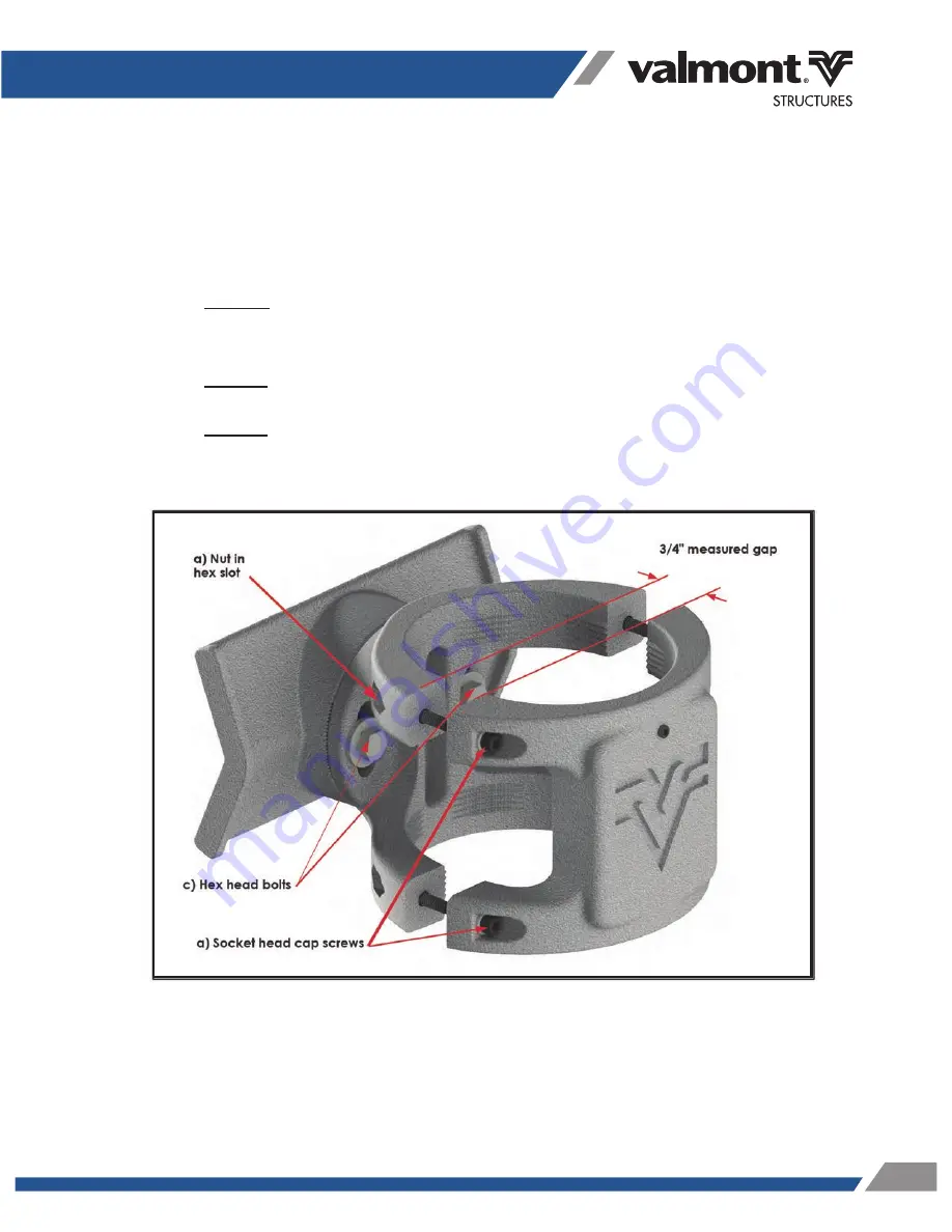
3 )  After banding the clamp to the arm:

b)

Loosen set screw above the Valmont

®

 “V”.

c)

Loosen two hex head bolts. (Note: The TR1 Clamp should now rotate 

within its set range of motion.)

Loosen all four socket head cap screws until you reach a 3/4" gap in the 

clamp halves (as indicated in Figure 3). Be sure that the nuts do not back 

off of the screws.

a)

Figure 3

5

Summary of Contents for Mitigator TR1

Page 1: ...Installation Specification I021 Patent No U S 9 470 288 Valmont MitIgator TR1 VIBRATION DAMPER INSTALLATION INSTRUCTIONS 1 800 825 6668 www ValmontStructures com...

Page 2: ......

Page 3: ...TR1 Damper is a sealed device containing strong internal magnets creating a magnetic field extending externally beyond the casing CAUTION This magnetic field can be harmful to pacemakers and other me...

Page 4: ...a level on the flat surface where the Valmont V is embossed b check that the TR1 Clamp is plumb vertically 0 1 degree from the axis of the arm before tightening the bands Band the clamp as close to t...

Page 5: ...V c Loosen two hex head bolts Note The TR1 Clamp should now rotate within its set range of motion Loosen all four socket head cap screws until you reach a 3 4 gap in the clamp halves as indicated in...

Page 6: ...he Damper as shown in figure 4 b Tighten set screw above the Valmont V to snug then an additional 1 4 turn Tighten all four socket head cap screws to hold the TR1 Damper in place making sure to mainta...

Page 7: ...cally attached to the TR1 Damper If any remove these objects which will render the TR1 Damper ineffective 5 Rotate the TR1 Clamp to be plumb vertically 0 1 degree and tighten the two hex head bolts to...

Page 8: ...red after the publication of this document Some images and specifications may not be identical to current production Valmont Structures reserves the right to change product design and specifications a...

Reviews: