10
Release 07/22
MashFlex
Wire Rope Safety Barrier
Wire Rope Safety Barrier
Wire Rope Safety Barrier
ASH LE
I N G A L C I V I L P R O D U C T S
ASH LE
I N G A L C I V I L P R O D U C T S
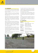
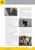
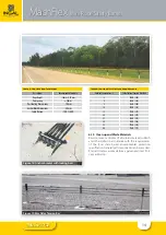
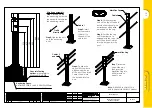
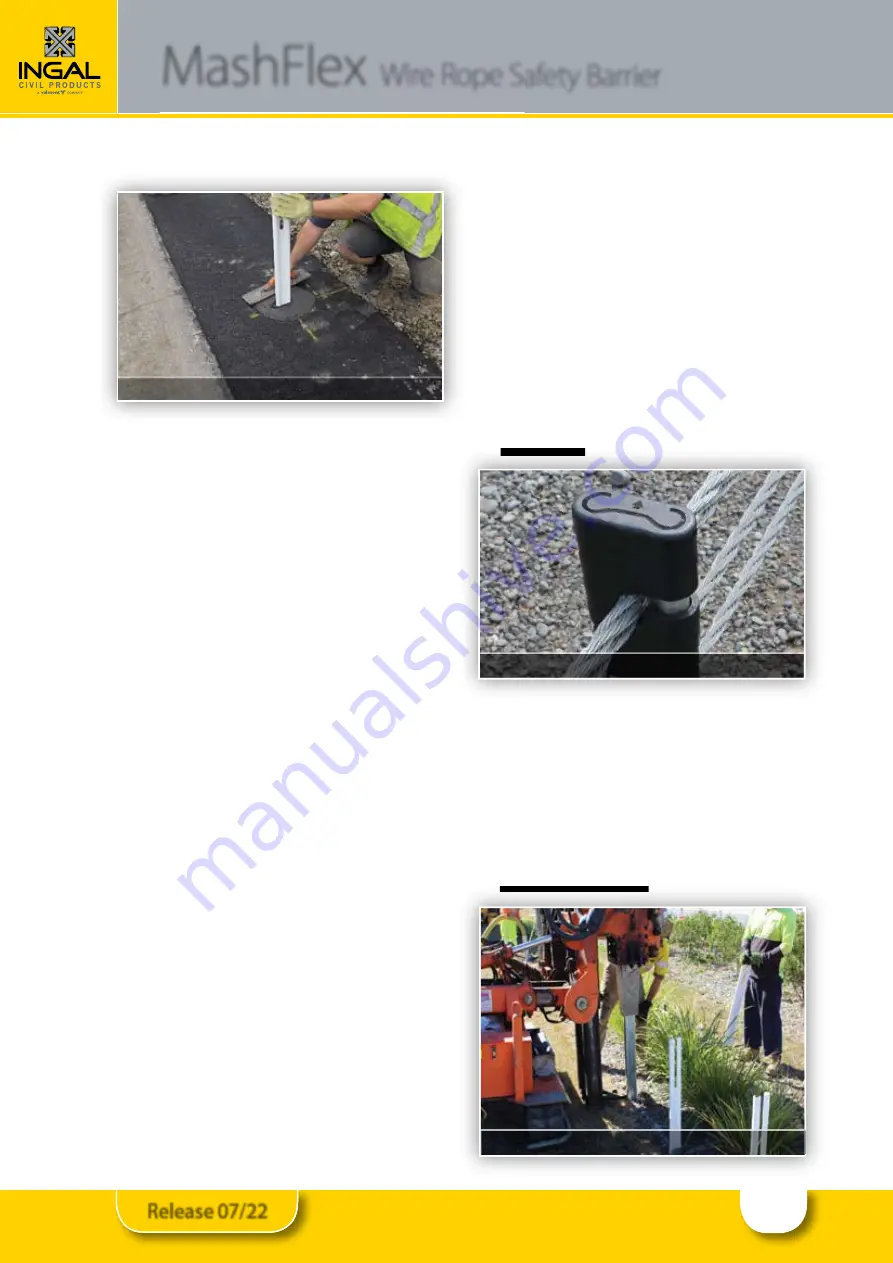
Figure 7: Trowelling of the Post Footing
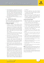
3. Insert the post footing reinforcement ring to a depth
providing 50mm of cover.
4. Insert the MashFlex post into the plastic HDPE sleeve
and push the plastic sleeve into the wet concrete so
that the top of the plastic sleeve is at ground level.
The posts are orientated so that the smooth face is
towards the traffic face.
5. Trowel the surface of the post footings and shape to
provide a slight fall away from the post sleeve. Any
doming should not exceed 20mm in height.
6.6 Driven Sleeve Post Footings
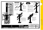
The Driven Sleeve Footings are driven directly into
the ground and should be vertical. Refer drawing
WR-MF-002 for minimum ground conditions, where
these conditions cannot be verified, a post pull-over
test can be conducted to verify suitability.
The sleeve installation process shall not cause damage
to the sleeve, such that it reduces the design life, or
introduces sharp edges.
Ensure the area has been inspected for underground
hazards and services prior to installation. Sleeves
should be driven to a depth appropriate for the
finished cable heights, as per drawing WR-MF-002.
6.7 Post on Baseplate Installation
Recommended ground beam dimensions and
reinforcement specifications for new concrete
foundations are provided in ICP drawing WR-MF-083,
available from your local Ingal Civil representative.
Two reinforcement options are given on this drawing
for convenience of install. Minimum 28-day strength
of concrete shall be 30MPa. Posts should be anchored
to a suitable concrete foundation via four M20 G5.8
studs, chemically anchored using Hilti HY-200R, refer
drawing WR-MF-003. Anchor studs shall be installed
in accordance with the manufacturer’s instructions..
6.8 Post Assembly Sequence
1. Slide the ground covers over each terminal and
longitudinal barrier post (figure 10).
2. Starting at the leading or high end of the fence,
connect the bottom cable to the anchor using a
temporary anchor connection and run out the cable
through the post slots to the far anchor and cut the
rope to length. Bottom cable should be inserted into
anchor bracket slot nearest the traffic.When a reel is
depleted, attach the end to the next reel via a tension
bay, refer section 6.9.
3. Insert steel cable spreader into terminal posts 1 and 2.
4. Assemble MashFlex cap onto longitudinal barrier
posts with particular attention to orientation of cap,
refer embossed post profile on top of cap (figure 8).
5. Starting at the leading end of the fence, connect the
second wire rope to the anchor bracket, with second
cable in second anchor bracket slot from traffic, and
run out the wire through the post slots up to the first
MashFlex post.
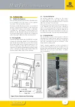
Figure 8: Cap orientation embossed on cap
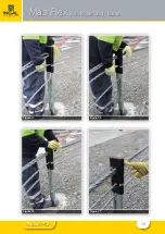
6. Lift MashFlex cap halfway and insert cable into second
slot until the cable can slide down post centre slot.
Repeat to end of run (figures 10 and 11).
7. Repeat these steps for cables 3 and 4 with both cables
inserted in top slot of MashFlex cap, in accordance
with drawing WR-MF-001 and figures 12 through 14.
Prior to installing the top cable, ensure the stainless
steel collar is installed between the top two cables of
the terminal posts only.
8. When all cables have been installed, fit the plastic cap
to the two terminal posts.
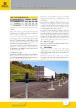
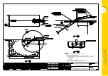
Figure 9: Driven Sleeve Installation
Summary of Contents for INGAL MashFlex MASH TL3
Page 11: ...11 Release 07 22 MashFlex Wire Rope Safety Barrier Figure 10 Figure 11 Figure 12 Figure 13...
Page 12: ...12 Release 07 22 MashFlex Wire Rope Safety Barrier Figure 14 Figure 15 Figure 16 Figure 17...
Page 19: ...19 Release 07 22...
Page 26: ...26 Release 07 22 Notes...
Page 27: ...27 Release 07 22 Notes...


