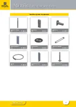
Wire Rope Safety Barrier
Wire Rope Safety Barrier
ASH LE
I N G A L C I V I L P R O D U C T S
ASH LE
I N G A L C I V I L P R O D U C T S
3
Release 07/22
MashFlex
Wire Rope Safety Barrier
3.0 Technical Data
3.1 MashFlex Performance
Wire rope safety barriers are classified as flexible barriers
and consideration must be given to the expected
movement of the barrier when impacted.
The design of a WRSB should include an assessment of
the mass of the impacting vehicle, its speed and angle
of impact. Whilst rigorous crash testing is undertaken
to evaluate the performance of roadside barriers, the
deflection results obtained during testing should not be
considered an exact distance, but rather as a single point
within the range of deflections that can be expected.
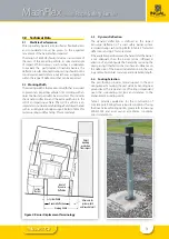
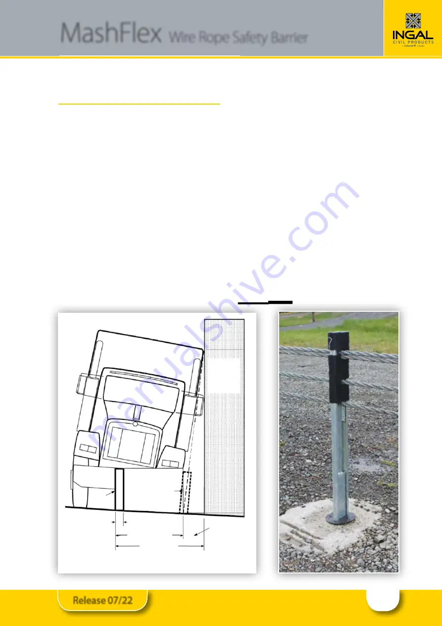
3.2 Working Width
The working width is the maximum width that is required
to prevent an impacting vehicle from colliding with an
object behind a road safety barrier system. This includes
the dynamic deflection and the extra width due to the
roll of an impacting vehicle. The roll of a vehicle is an
important consideration in shielding a fixed object hazard
such as a utility pole or bridge support. Refer to Table 2 for
tested working widths and Fig. 2 for more detail.
3.3 Dynamic Deflection
The dynamic deflection is defined as the largest
transverse deflection of a road safety barrier system
recorded during crash testing. Refer to Table 2 for tested
deflections and Fig. 2 for more detail.
If the available space between the hazard and the barrier
is not adequate, then the barrier can be stiffened in
advance of, and alongside the hazard by reducing the
post spacing. Other factors that can have an influence on
the deflection of the barrier include tension in the wire
rope cables, horizontal curvature and installation length.
3.4 Footing Selection
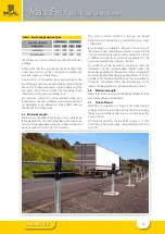
The post footing provides lateral support to the post
during impact ensuring the post yields by bending near
ground level. The type and size of footing is dependant
upon the surrounding soil type and distance to the
embankment rounding point.
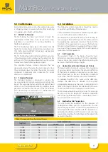
Table 1 provides guidelines for the construction of
concrete post footings for varying site conditions. If using
the Driven Sleeve footing option, please refer to drawing
WR-MF-002 and asset owner acceptance conditions
prior to installation.
Figure 2: Barrier Displacement Terminology
Allowance for
system width
and/or vehicle roll
Working Width
System Width
Dynamic Deflection
(may be 0m with rigid barriers)
Safety
Barrier
Limit of
Dynamic
Deflection
Initial position of barrier
Ve
hic
le
ro
ll i
s s
lop
e l
ine
Object
requiring
protection
from impact
De
fle
cte
d
po
sit
ion
of
ba
rri
er
Summary of Contents for INGAL MashFlex MASH TL3
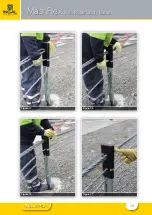
Page 11: ...11 Release 07 22 MashFlex Wire Rope Safety Barrier Figure 10 Figure 11 Figure 12 Figure 13...
Page 12: ...12 Release 07 22 MashFlex Wire Rope Safety Barrier Figure 14 Figure 15 Figure 16 Figure 17...
Page 19: ...19 Release 07 22...
Page 26: ...26 Release 07 22 Notes...
Page 27: ...27 Release 07 22 Notes...


