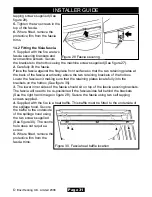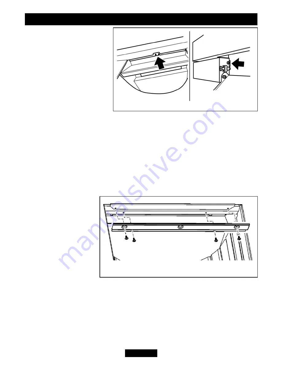
tapping screws supplied (See
figure 29).
5.
Tighten the two screws in the
top of the fascia.
6.
Where fitted, remove the
protective film from the fascia
trims.
14.2 Fitting the Visia fascia.
1.
Supplied with the fire are two
fascia securing brackets and
two machine screws. Secure
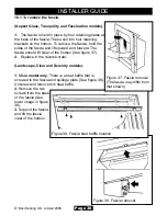
the brackets to the hotbox using the machine screws supplied (See figure 27).
2.
Carefully lift the fascia.
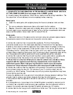
Place the fascia against the fireplace front surface so that the two retaining plates at
the back of the fascia are directly above the two retaining brackets of the hotbox.
Lower the fascia unit making sure that the retaining plates locate fully into the
brackets on the hotbox (See figure 36).
3.
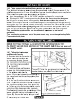
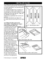
The lower inner sides of the fascia should sit on top of the fascia securing brackets.
The fascia will need to be re-positioned if the fascia sides fall behind the brackets
(See the right hand image in figure 29). Secure the fascia using two self tapping
screws supplied.
4.
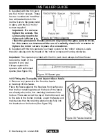
Supplied with the fire is a heat baffle. This baffle must be fitted to the underside of
the spillage hood. Secure
the baffle to the underside
of the spillage hood using
the two screws supplied
(See figure 30). The centre
hole does not require a
screw.
5.
Where fitted, remove the
protective film from the
fascia trims.
Page 31
©
Baxi Heating U.K. Limited 2008.
INSTALLER GUIDE
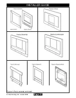
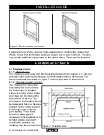
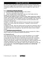
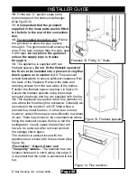
Figure 29 Fascia securing.
Figure 30. Fascia heat baffle location

