background image

3

Safety Precautions

!

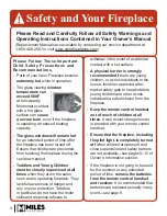
Children and adults should be 

ALERTED

 to the hazards 

of high surface temperature and should 

STAY AWAY

 to 

avoid burns or clothing ignition.

YOUNG CHILDREN

 should be 

CAREFULLY


SUPERVISED

 when they are in the same room as the 

appliance. Toddlers, young children and others may 
be susceptible to 

ACCIDENTAL CONTACT BURNS

A physical barrier is recommended if there are at-risk 
individuals in the house. To restrict access to a fi replace 
or stove, 

INSTALL AN ADJUSTABLE SAFETY GATE


to keep toddlers, young children and other at-risk 
individuals out of the room and away from hot surfaces.

DO NOT 

place furniture or any other combustible 

household objects within 36” of the fi replace front.

READ

 and 

UNDERSTAND

 all instructions carefully 

before starting the installation. 

FAILURE TO FOLLOW


these installation instructions may result in possible fi re 
hazard and will void the warranty.

Prior to the fi rst fi ring of the fi replace, 

READ

 the 

Owner’s Information section of this manual.

DO NOT USE 

this appliance if any part has been under 

water. Immediately, 

CALL

 a qualifi ed service technician 

to inspect the unit and to replace any part of the control 
system and any gas control that has been under water.

THIS UNIT IS NOT FOR USE WITH SOLID FUEL.

Installation and repair should be 

PERFORMED

 by a 

qualifi ed service person. The appliance and venting 
system should be 

INSPECTED

 before initial use and at 

least annually by a professional service person. More 
frequent cleaning may be required due to excessive 
lint from carpeting, bedding, etc. It is 

IMPERATIVE

 that 

the unit’s control compartment, burner, and circulating 
air passageways 

BE KEPT CLEAN 

to provide for 

adequate combustion and ventilation air.

Always 

KEEP

 the appliance clear and free from 

combustible materials, gasoline, and other fl ammable 
vapors and liquids.

NEVER OBSTRUCT 

the fl ow of combustion and 

ventilation air. Keep the front of the appliance 

CLEAR


of all obstacles and materials for servicing and proper 
operation.

Due to the high temperature, the appliance should be 

LOCATED

 out of traffi c areas and away from furniture 

and draperies.

Clothing or fl ammable material 

SHOULD NOT BE 

PLACED 

on or near the appliance.

This unit MUST be used with a vent system as 
described in this installation manual. 

NO


OTHER

 vent 

system or components 

MAY BE USED

.

This gas fi replace and vent assembly 

MUST

 be vented 

directly to the outside and 

MUST


NEVER

 be attached 

to a chimney serving a separate solid fuel burning 
appliance. Each gas appliance 

MUST USE 

a separate 

vent system. Common vent systems are 

PROHIBITED

.

INSPECT

 the external vent cap on a regular basis to 

make sure that no debris, plants, trees, shrubs are 
interfering with the air fl ow.

DO NOT OPERATE

 this appliance with the glass door 

removed, cracked, or broken. Replacement of the glass 
door should be performed by a licensed or qualifi ed 
service person. 

DO NOT

 strike or slam the glass door.

The glass door assembly 

SHALL ONLY 

be replaced 

as a complete unit, as supplied by the fi replace 
manufacturer. 

NO SUBSTITUTE

 material may be used.

BARRIER DESIGNED TO REDUCE THE RISK OF 

BURNS

 from the hot viewing glass is provided with 

this appliance and 

SHALL BE INSTALLED

 for the 

PROTECTION OF CHILDREN

 and other 

AT-RISK 

INDIVIDUALS

.

DO NOT USE 

abrasive cleaners on the glass door 

assembly. 

DO NOT ATTEMPT

 to clean the glass door 

when it is hot.

If the barrier becomes damaged, the barrier 

SHALL BE 

REPLACED

 with the 

MANUFACTURER’S BARRIER


for this appliance.

TURN OFF

 the gas before servicing this appliance. 

It is recommended that a qualifi ed service technician 
perform an appliance check-up at the beginning of each 
heating season.

Any safety screen, guard or barrier removed for ser-
vicing the appliance, 

MUST BE REPLACED 

prior to 

operating the appliance.

BE CAREFUL

 not to put any decorating objects 

sensitive to heat to close above or around the fi replace 
as it gets very hot when operating.

DO NOT 

use this heater as a temporary source of heat 

during construction.

This appliance is a 

DOMESTIC ROOM-HEATING AP-

PLIANCE

. It must not be used for any other purposes 

such as drying clothes, etc.

State of California. Proposition 65 Warning. 

Fuels 

used in gas, wood-burning or oil fi red appliances, 
and the products of combustion of such fuels, contain 
chemicals known to the State of California to cause 
cancer, birth defects and other reproductive harm. 
California Health & Safety Code Sec. 25249.6.

The glass door assembly 

MUST

 be in place and sealed 

before the unit can be placed into safe operation.

Summary of Contents for 1100IN

Page 1: ...te the installation A barrier screen is provided with the trim kit Refer to the manual supplied with the trim for installation HOT GLASS WILL CAUSE BURNS DO NOT TOUCH GLASS UNTIL COOLED NEVER ALLOW CH...

Page 2: ...8 Using Handset Wall Holder 9 Locating Lighting Operation and Rating Information Card 9 Servicing Your Fireplace 9 Operating Your Fireplace 9 How to Turn Your Fireplace OFF including pilot 10 How to E...

Page 3: ...BE PLACED on or near the appliance This unit MUST be used with a vent system as described in this installation manual NO OTHER vent system or components MAY BE USED This gas fireplace and vent assemb...

Page 4: ...e A physical barrier is strongly recommended if there are young children or at risk individuals in the house Install an approved after market safety gate to keep toddlers young children and other at r...

Page 5: ...y installed by Dealer Name ________________________________ Phone Number _______________________________ Should you encounter an operational problem call your dealer immediately Do not try to repair t...

Page 6: ...cloth Most paper towels and synthetic materials are abrasive to ceramic glass and should be avoided Our dealers have had good results from the products listed below We cannot however guarantee the res...

Page 7: ...ll the barrier screen on the trim a 1130 1135 1140 1145 trims Insert the screen s top tabs in the slots on the underside of the convection baffle or heatshield then insert the screen s bottom tabs in...

Page 8: ...Holder Your fireplace equipment includes a wall holder to store the handset If it hasn t be installed refer to the instructions further on in this manual for the installation Ensure the screen is sec...

Page 9: ...r battery compartment s cover off 4 Replace the batteries with 4 AA alkaline batteries orienting them as indicated inside the compartment 5 Replace the cover 6 Put the receiver back in its location at...

Page 10: ...handle is parallel with the pipe The gas is off when the handle is perpendicular with the pipe Owner s Information How to Ensure Your Fireplace Cannot Be Turned ON Inadvertently You can use one of the...

Page 11: ...i t c n u f o n s i e r e h t d e s s e r p s i n o t t u b d e t a v i t c a e d a f I and two horizontal bars are displayed NOTE s e i r e t t a b f o e g n a h c r e t f a t c e f f e n i s n i a...

Page 12: ...and call your local service technician or gas supplier See page 17 for more information OFF STANDBY MODE PILOT FLAME Handset Press and hold button TO TURN OFF FIRE ON AM PM OFF Handset NOTE There is a...

Page 13: ...ntil displayed and hour flashes Press button and countdown time disapear At end of countdown time period the fire turns off The CountdownTimer only works in Manual Thermostatic and Eco Modes Maximum c...

Page 14: ...s button NOTE Either continue to PROGRAM 2 and set on and off times or stop programming at this point and PROGRAM 2 re mains deactivated NOTE PROGRAM 1 and 2 use the same on Thermostatic and off tempe...

Page 15: ...PSHUDWXUH LQ WKH UHFHLYHU LV KLJKHU WKDQ 7KH PDLQ EXUQHU WXUQV EDFN RQ PDQXDOO RU LQ 7KHUPRVWDWLF 0RGH RQO ZKHQ WKH WHPSHUDWXUH LV EHORZ LWK ORZ EDWWHU SRZHU LQ WKH UHFHLYHU WKH V VWHP VKXWV RII WKH I...

Page 16: ...Doors n a Optional Accessories Trim Optional Accessories 1100 and 1150 units 1147CMS Cast Mantel Surround 1148CIR Cast Inlay Reeds 1148CIS Cast Inlay Sheffield 1148CIT Cast Inlay Tatch Conversion Kit...

Page 17: ...lear out any gas then smell for gas including near the floor If you smell gas STOP Follow B in the safety information above on this label If you don t smell gas go to the next step 3 AUTOMATIC IGNITIO...

Page 18: ...d a battery operated carbon monoxide detector with an alarm shall be installed 2 APPROVED CARBON MONOXIDE DETECTORS Each carbon monoxide detector as required in accordance with the above provisions sh...

Page 19: ...ded with the appliance or equipment installation instructions and 2 The special venting systems shall be Product Approved by the Board and the instructions for that system shall include a parts list a...

Page 20: ...r in the absence of local codes with the National Electrical Code ANSI NFPA 70 or the Canadian Electrical Code CSA C22 1 High Altitude Installations Input ratings are shown in BTU per hour and are cer...

Page 21: ...al outlet field convertible to horizontal outlet Remote Handset Wall Holder W W W Wall ll ll ll F F F Fi i ini i i ish h h h Any wall finishes applied over non combustible board must be also non combu...

Page 22: ...For all other trims this is the maximum required and may be reduced if positioning the unit forward of the framing to accomodate thickness of non combustible material over top of non combustible boar...

Page 23: ...appliance Mantel Projection from Face of Cement Board Mantel Height from Bottom of Unit Ceiling 65 Min to Ceiling 49 47 45 43 41 4 minimum to combustible floor or hearth See Hearth Requirements secti...

Page 24: ...hed Wall Shading denotes allowable location for combustible mantel legs FIREPLACE Depth 1 2 3 4 5 6 or greater Clearance 3 4 5 6 7 8 Note Right Side Clearances are the same Combustible Sidewall Mantel...

Page 25: ...or other combustible material other than wood flooring the appliance shall be installed on a metal or wood panel extending the full width and depth of the appliance WARNING SAFETY WARNING The H5 is a...

Page 26: ...mal break 2 Minimum hearth projection is determined by a combination of the height of the hearth above the surface of combustible floor or carpet and the distance between the hearth and the bottom of...

Page 27: ...should be set back 1 2 behind front face of framing otherwise topface of shims may be visible Surface of Combustible Floor or Carpet Bottom of fireplace ood is Allowed directly below fireplace ny shi...

Page 28: ...ttom of the unit must be non combustible Rear Vent 16 1 2 Top Vent 17 1 2 May be reduced by thickness of additional non combustible wall finish applied on top of 1 2 non combustible board when using t...

Page 29: ...ents Minimum Non Combustible Board Dimensions Minimum coverage area of non combustible board Any wall finish applied to shaded area must be non combustible We recommend extending the non combustible b...

Page 30: ...les around vertical vent pipe Approx 9 1 4 235 mm from back surface of wall finish to front surface of appliance case w no vent offset 13 3 4 349 mm PARTIAL SHELF top outlet 1 2 thick non combustible...

Page 31: ...nting Considerations Horizontal Takeoff Notes ALL venting considerations Dimensions of venting are based on using Dura Vent elbows Elbow curve radius dimensions will vary when using other brands In ge...

Page 32: ...up to 8 inches in thickness A non combustible wall can be of any thickness up to the maximum horizontal run of vent pipe allowed for the particular installation Framing Vent in Combustible Walls Ceil...

Page 33: ...IECE WALL THIMBLE PIPE LENGTH PIPE LENGTH PIPE LENGTH PIPE LENGTH 90 ELBOW 90 ELBOW CEILING FIRESTOP ATTIC FIRESTOP ATTIC INSULATION SHIELD FLASHING STORM COLLAR VERTICAL TERMINATION Co axial Venting...

Page 34: ...roof termination is 6 feet 4 Any combination of rise and run can be used as long as they are within the allowable limits shown on the chart below 5 A maximum of 4 x 90 degrees elbows or equivalent 2...

Page 35: ...depends on the vertical rise in the venting system and to a lesser degree the horizontal run and number of elbows The amount of restriction is based on laboratory tests The ideal restrictor position m...

Page 36: ...bly located within 15 feet 4 6 m below the terminal 36 90 I Clearance to service regulator vent outlet 36 90 J Clearance to non mechanical air supply inlet to the building or the combustion air inlet...

Page 37: ...ey The appliance must not be connected to a chimney flue serving a separate solid fuel burning appliance Requires the Valor Co Axial to Co Linear appliance Adapter 1156CLA two lengths of 2 ply one 3 a...

Page 38: ...linear adapter Dimensions shown are with Valor 1156 co linear adapter Installation For installation of the adapter to the appliance see the instructions supplied with the 1156CLA Co linear Venting 115...

Page 39: ...older 18 Instruct the homeowner on the operation and maintenance of the fireplace 19 Finish the wall around the fireplace 20 Install the surround trim and barrier screen Installation Planning Applianc...

Page 40: ...board may be used beyond the perimeter of the cement board although it is preferable not to change materials to help avoid cracking Finishing around trims Additional non combustible material such as...

Page 41: ...rying from a saturated condition Running the fireplace for an extended period before final finishing will help drive out moisture Always pre drill screw holes through cement board and use screws with...

Page 42: ...t shield Installation Unpack Appliance Beware of sharp edges Wear gloves 1 Remove the cardboard wrapping and the wood pallet from the appliance and discard 2 Unpack any loose items from around the app...

Page 43: ...ide 1 To remove the window locate the levers on each side of the window towards the top Using your finger pull the lever towards you and unhook it from the window frame bracket 2 Gently pull the top o...

Page 44: ...in the framing Wall finishes are then applied over top of the flanges and butted up to the frame of the 1130 Install Appliance for 1130 Fixed Framing Kit Appliance Depth in Framing with 1130 Fixed Fra...

Page 45: ...ottom of the appliance See Hearth Requirements section of this manual The non combustible hearth in front of the appliance if within 4 of the bottom of the appliance must include the 1 2 Micore insula...

Page 46: ...ide panels as indicated 3 screws per side 5 Install the upper panel as indicated 2 screws 6 Slide the appliance into the framing and fix it to the studs on each side 6 fixing points per side 7 Set asi...

Page 47: ...e for 3 and 4 Sided Trim Doors or Cast Mantel Appliance Depth in Framing with 3 and 4 Sided Trims Doors 3 and 4 Sided Trims Doors adjustable position wall finish thickness up to 3 4 1 2 non combustibl...

Page 48: ...must be considered Without hearth In the case where there is no hearth the bottom of the appliance must be raised at least 4 inches 102 mm above any combustible floor in front With hearth The bottom o...

Page 49: ...the framing Make sure that the unit is at the right height with consideration to the height of the hearth or combustible flooring When setting the position of appliance within framing the front surfa...

Page 50: ...neral Requirements The optional 1195CFK kit includes a three prong grounded plug to plug into a grounded receptacle also included with the kit to be installed within the fireplace enclosure by a quali...

Page 51: ...valve during any pressure testing of the gas supply pip ing system at test pressures equal to or less than 1 2 psig 3 5 kPa Failure to either disconnect or isolate the appliance during pressure testi...

Page 52: ...lace the rear panel against the back of the firebox behind the rail retainers at bottom and behind the side panel already installed Note If you are installing the optional 1105RGL Reflective Glass lin...

Page 53: ...irebox for natural gas NG fire The log covers both holes LPG fire Place the log s front peg in the hole closest to the left side wall for propane gas LPG fires Installation 2 Place the right log on th...

Page 54: ...n Vacuum area after installation Installation 4 Carefully spread shale in the cavity of the ceramic burner You can also add some shale on the edge outside of the burner plate cavity NOTE Ensure the ar...

Page 55: ...hich contains 1 glass platform 2 platform retainers 1 bag of clear 1 2 fireglass Gloves recommended to manipulate glass Installation Carefully unpack the kit Wear gloves to handle the fireglass 1 Inst...

Page 56: ...tray over the ceramic burner 2 Remove the existing pilot shield 2 screws 3 Place the pilot cover on top of the metal tray spanning over the pilot cut out Installation 4 Carefully fill the metal tray...

Page 57: ...this gap generallly produces a taller rear flame while opening up this gap can help eliminate tall stringny flames hitting the roof panel As the vent height affects the rear flame appearance this gap...

Page 58: ...as indicated 4 Place the left hand base log on the platform locating it on the key as indicated 5 Place the center base log locating its notch on the key in the ember bed as indicated 6 Place the rig...

Page 59: ...d Rest the front end of the log on top of the left base log as indicated 8 Place the right hand cross log locating its notch on the key on the top of the rear log as indicated Rest the front end of th...

Page 60: ...tion is not covered by the Valor warranty DANGER The window unit must be correctly installed fastened and sealed after servicing or serious bodily injury and or damage to the appliance may result To e...

Page 61: ...ET button until you hear one short and one long beeps After the second beep release the reset button 4 Within the subsequent 20 seconds press the button on the remote handset until you hear two short...

Page 62: ...ceramic effects glow Decreasing aeration will cause the flames to appear more yellow or orange showing less ceramic effects glow Too little aeration may result in black carbon forming on logs or roof...

Page 63: ...is provided as an optional feature for those customers who wish to mount the remote handset to the wall To install the holder to the wall find a convenient location see below and use the hardware pro...

Page 64: ...ctrode Cable Receiver Combination Control Valve GV60 Wiring Diagram Button RESET Battery Compartment 4 AA Batteries Optional Fan 1195CFK Control Module Yellow SPARK SPARK SW Pilot Thermocurrent Interr...

Page 65: ...M CFAA3 95090390 Co linear Flex Connector 46DVA ADF Co axial to Co linear Adapter 46DVA GCL6 TM 4CAA6 4DCAB336 1156CLA5 6 9401064336 Co linear to Co axial Adapter 46DVA GK TM 4CTA 4DCAT33 Aluminum Fle...

Page 66: ...SK 949606001 Masonry Flashing TF 4MF New Siding Flashing 658NSFK Various Venting System Parts Wall Thimble 46DVA WT 4DT WT TM 4WT SV4RSM 4DWT 949064U Storm Collar 46DVA SC 4DT SC TM SC SV4AC 4DSC 9496...

Page 67: ...damage to the unit due to i Improper installation operational or environmental conditions ii Inadequate ventilation in the area or competition for air from other household equipment or appliances iii...

Page 68: ...skets module plate LH 4003927 33 Pilot sealing plate 4002910 34 Valve to injector pipe assembly 4004065 35 Valve mount 4003956 Code Description Part Number 36a GV60 valve assembly NG 1100 4004498X 36b...

Page 69: ...15LSL Fluted Black Liner Set 1125FBL 76 Rear panel Valor Red Brick 4003264 Ledgestone 4003246 Fluted Black 4003258 77 LH side panel Valor Red Brick 4003262 Ledgestone 4003244 Fluted Black 4003256 78 R...

Page 70: ...46 1 2 3 4 4 5 6 6 7 7 8 9 10 11 11 13 14 74 16 17 19a 19b 19c 19d 20 21 22 23a 23b 23c 24 25a 25b 26 27 28a 28b 29 37 39 40 41 42 43 44 47 48 49 50 51 52 53 54 55 56 57 58 59 60 60 61 62 63 64 65 66...

Page 71: ...vided will be used for customer records only Online Warranty registration at www valorfireplaces com Cut out page fill information and mail to Miles Industries Ltd Fireplace Information Model Number 1...

Page 72: ...hut Thank you for choosing a Valor Product Postage needed Miles Industries Ltd 190 2255 Dollarton Highway North Vancouver BC V7H 3B1 Canada Fold here Online Warranty registration at www valorfireplace...

Reviews: