
5
Operating Your Fireplace for the First Time
When operating your new fi replace for the fi rst time,
some vapors may be released due to the burning of
curing compounds used in the manufacture of the
appliance. They may cause a slight odor and could
cause the fl ames to be the full height of the fi rebox, or
even slightly higher, for the fi rst few hours of operation.
It is also possible that these vapors could set off any
smoke detection alarms in the immediate vicinity.
These vapors are quite normal on new appliances. We
recommend opening a window to vent the room. After
a few hours use, the vapors will have disappeared and
the fl ames will be at their normal height.
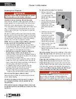
Flame Supervision Device
For your safety, this appliance is fi tted with a fl ame
supervision device which will shut-off the gas supply
if, for any reason, the pilot fl ame goes out. This device
incorporates a fi xed probe, which senses the heat
from the pilot fl ame. If the probe is cool, the device will
prevent any gas fl ow unless manually lighting the pilot.
See full lighting instructions on page 17 of this manual.
Owner’s Information
This manual and particularly the preceeding
and following pages contain very important
information regarding the safe operation of your
fi
replace as well as maintenance instructions.
Read carefully BEFORE operating your
fi
replace
and pay special attention to the SAFETY
WARNINGS.
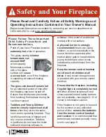
A heating gas appliance does require safe handling
and for this reason, we very strongly recommend that
no children be allowed to touch the fi replace and its
controls at all times.
Do install a screen or barrier
in front of the
fi
replace to protect your children
against severe burns.
Thank You ...
For purchasing a Valor by Miles Industries. Your new
radiant gas heater is a technical appliance that must
be installed by a qualifi ed dealer. Each Valor fi replace
is fully tested during the production process for your
safety and comfort.
Your unit has been professionally installed by:
Dealer Name: ________________________________
Phone Number :_______________________________
Should you encounter an operational problem, call
your dealer immediately.
Do not try to repair the unit as you may cause an
injury or damage the
fi
replace.
!
WARNING
EXTREMELY HOT!!!
•
READ the SAFETY information on pages
3 and 4 of this manual BEFORE operating
your gas heater.
• Some parts of your fi replace are
EXTREMELY
HOT
, particularly the
GLASS
window.
•
DO NOT LET CHILDREN
touch the glass or
any parts of your fi replace
even after it is
turned off
as it is still hot.
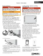
•
USE THE BARRIER SCREEN provided with
the trim or a GATE
to reduce the risk of severe
burns.
• Keep the remote control handset
OUT OF
REACH
of children.
•
HOT WALL SURFACES!
The wall directly above
the fi replace is
VERY HOT
when the fi replace
heats. It is constructed of non-combustible
materials and although safe, it may reach
temperatures
in excess of 200º F
depending
on choice of trims.
DO NOT TOUCH IT!
•
HOT HEARTH/FLOOR SURFACE!
The
hearth or fl oor directly in front of the fi replace
is
VERY HOT
when the fi replace heats. Even
if constructed of non-combustible materials,
and although safe, it may reach temperatures
in excess of 200º F
depending on choice of
materials.
DO NOT STEP ON IT!
•
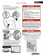
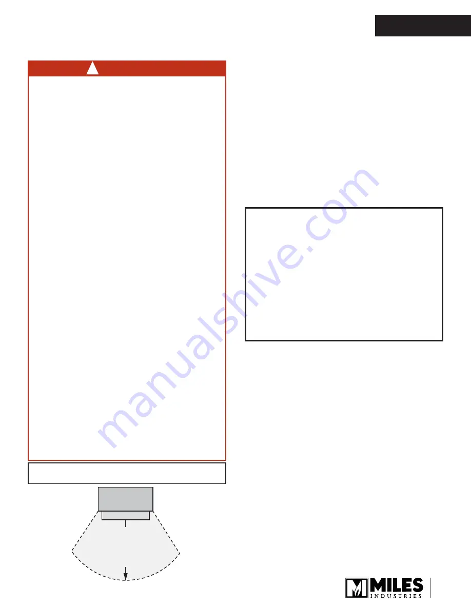
• Some materials or items, although safe, may
Some materials or items, although safe, may
discolor, shrink, warp, crack, peel, and so on
discolor, shrink, warp, crack, peel, and so on
because of the heat produced by the fi replace.
because of the heat produced by the fi replace.
AVOID PLACING
AVOID PLACING
candles, paintings, photos,
candles, paintings, photos,
and other items
and other items
SENSITIVE TO HEAT
SENSITIVE TO HEAT
within
36 inches (0.9 m) around the fi replace.
•
• Solid wood fl ooring in front of the fi replace (if
Solid wood fl ooring in front of the fi replace (if
allowed) may shrink during the heating season
allowed) may shrink during the heating season
due to heat.
due to heat.
Performance of LPG appliances may be affected by
the quality of commercial gas supplied in your area.
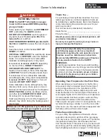
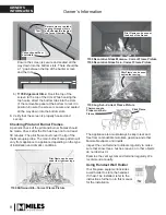
Do not put
furniture or other objects
in this space in front of
the fireplace:
36” (0.9 m)
Fireplace
Hearth
OWNER’S
INFORMATION


