background image

INSTALLER’S GUIDE

Page 10

2.17

Propane gas appliances must not be installed in a room that is built entirely below

ground level (See BS 5871 Part 2).

2.18

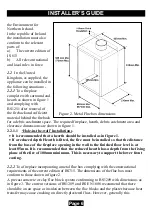
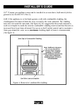
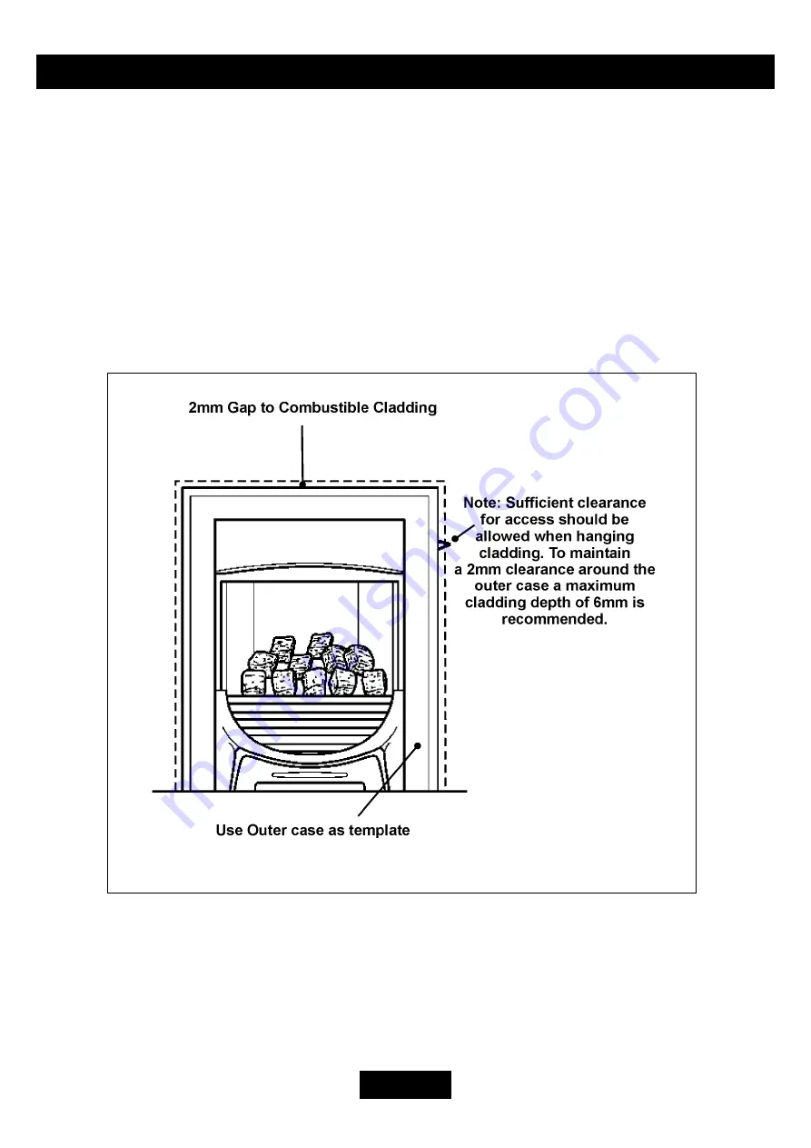
If the appliance is to be fitted against a wall with combustible cladding, the

cladding must be removed from the area covered by the outer surround. The cladding
must also not touch the surround. (See figure 4). We suggest that the actual surround is
used as a template to mark the area for combustible cladding removal and that this area is
increased by at least 2mm all round. For access to the Fireslide control and to maintain a
2mm gap around the outer case a 

maximum

 cladding depth of 6mm is recommended

(See figure 4).

Figure 4. Removal of combustible cladding

Summary of Contents for C1

Page 1: ...OF IRELAND IE ONLY INSTALLER Please leave this guide with the owner Manufactured exclusively for British Gas Scottish Gas by Valor Heating For Service Phone 0845 960 5040 Because our policy is one of...

Page 2: ...4 14 2 Check For Spillage 35 14 3 Flame Supervision Spillage Monitoring System 35 15 FINAL REVIEW 37 16 SERVICING PARTS REPLACEMENT 38 16 1 CHECKING THE AERATION SETTING OF THE BURNER 38 16 2 To Remov...

Page 3: ...heavy then obtain assistance When lifting always keep your back straight Bend your legs and not your back Avoid twisting at the waist It is better to reposition your feet Avoid upper body top heavy b...

Page 4: ...ardous waste and may be disposed of at a tipping site licensed for the disposal of industrial waste Protective clothing is not required when handling these articles but we recommend you follow the nor...

Page 5: ...to recognised standards In the United Kingdom the installation must also be in accordance with All the relevant parts of local regulations All relevant codes of practice The relevant parts of the cur...

Page 6: ...as in figure 1 If a reduced depth Hearth is fitted the fire must be installed so that the distance from the base of the fireplace opening in the wall to the finished floor level is at least 85mm It is...

Page 7: ...d be noted that as with many appliances sharp bends or horizontal runs in metal flues at the top of the system can be a cause of problems in these types of installation 225mm x 225mm conventional bric...

Page 8: ...the fireplace opening is an underfloor draught type it must be sealed to stop any draughts 2 10 The appliance must be mounted behind a non combustible hearth N B conglomerate marble hearths are consi...

Page 9: ...tains a bath or shower or where steam is regularly present 2 15 An extractor fan may only be used in the same room as this appliance or in any area from which ventilation for the appliance is taken if...

Page 10: ...from the area covered by the outer surround The cladding must also not touch the surround See figure 4 We suggest that the actual surround is used as a template to mark the area for combustible cladd...

Page 11: ...etary terminals must comply with BS 715 or BS 1289 Any terminal or termination must be positioned in accordance with BS 5440 Part 1 to ensure that the products of combustion can be safely dispersed in...

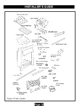
Page 12: ...box side flanges 1 Strip of floor sealing tape 6 Fibre plugs 4 Woodscrews 2 Fire retaining cables 2 Cable clamps 4 Eyebolts 1 Rubber grommet 1 Knurled shouldered screw for control linkage fixing 2 Sur...

Page 13: ...INSTALLER S GUIDE Page 13 Figure 6 Pack contents...

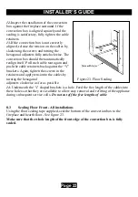
Page 14: ...wall with combustible cladding the cladding must be removed from the area covered by the outer surround The cladding must also not touch the surround See figure 4 We suggest that the actual surround i...

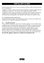
Page 15: ...surface of the metal flue box must be covered with a 100mm layer of mineral wool or equivalent insulation See figure 2 4 2 Fireplace Flue Pull Close all doors and windows in the room in which the appl...

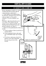
Page 16: ...figure 8 The positive terminal is to the bottom as you insert Rotate the control pivot bracket as far as it will go This should close the ignition circuit Sparks should be seen tracking from the elec...

Page 17: ...inside the fireplace is required then before the appliance is fitted into the fireplace it will be necessary to extend the supply line so that it will project through the chosen removable circular pan...

Page 18: ...r of the convection box Decide which one of these is to be used for rear entry Using a suitable tool apply pressure to the centre of the removable circular panel There is a grommet in the installation...

Page 19: ...emoved After removal conduct the spillage check again The restrictor is packed loose with the appliance and is fixed with three screws See figure 14 6 There is a length of self adhesive foam seal supp...

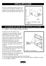
Page 20: ...eplace in the position in which it is to be permanently installed If a concealed connection is being used insert the convection box into the fireplace feeding the supply pipe through the pierced hole...

Page 21: ...cables 3 Insert a fibre plug into each hole Use the fibre plugs supplied with this appliance Never use plastic plugs instead of the fibre plugs supplied Screw the eyebolts into the plugs Make sure th...

Page 22: ...a hole into the fireplace floor through each of the two holes in the base of the convection box using a no 12 masonry drill See figure 21 9 Insert a fibre plug into each hole Use the rawlplugs supplie...

Page 23: ...push the cable retainers back against the V brackets Again tighten the screws in the retainers and apply tension to the cables by turning the hexagonal adjusters clockwise as far as possible 14 Undern...

Page 24: ...lose the ignition circuit and simultaneously open the gas tap allowing the gas to flow to the pilot Wait a few seconds while the air is purged The electronically generated sparks should light the pilo...

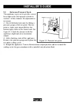
Page 25: ...a pressure gauge at the test point The test point is on the pipe situated below the bottom right corner of the burner unit See figure 25 Check the pressure with the appliance alight and set at maximum...

Page 26: ...flat against the back face of the burner compartment See figure 26 3 Remove four screws from the spillage plate sides See figure 27 4 Remove the spillage plate by lifting it forward 5 Fit the ceramic...

Page 27: ...figure 28 Swing the bottom control linking bar towards the centre of the fire to clear the right side of the surround Slide the surround unit sideways if necessary to align the bottom fixing holes wi...

Page 28: ...rackets See figure 31 Installer Note that the small round holes in the burner plaques that will be covered by the base coal are not gas burner ports They are simply a consequence of the plaque manufac...

Page 29: ...t 90 to the rear of the firebox 7 Hold coal A upright with the arrow pointing to the top Locate coal A as shown in figure 33 8 Locate coals B to E so that they are firmly seated in the valleys in the...

Page 30: ...Hold coal E upright with the arrow pointing to the top Locate coal E as shown in figure 37 13 Hold coal F upright with the arrow pointing to the top Locate coal F as shown in figure 38 14 This will c...

Page 31: ...th the arrow pointing to the top Locate coal G as shown in figure 39 17 Hold coal H upright with the arrow pointing to the top Locate coal H as shown in figure 40 18 Hold coal I upright with the arrow...

Page 32: ...l J as shown in figure 42 20 Hold coal K upright with the arrow pointing to the top Locate coal K as shown in figure 43 21 Hold coal L upright with the arrow pointing to the top Locate coal L as shown...

Page 33: ...re front casting are in the outer threaded holes If they are in the inner holes relocate them See figure 45 13 2 Locate the two screw heads through the keyhole slots at the inner sides of the surround...

Page 34: ...ain in this position to ignite the pilot The burner should ignite at its lowest setting within 4 seconds of the pilot igniting Keep at this position for a further 10 seconds to allow the pilot flame t...

Page 35: ...e fireplace surround If the sealing is satisfactory but the appliance is installed with the flue restrictor see section 7 point 8 remove the restrictor reseal the appliance and retest If smoke is stil...

Page 36: ...n electromagnetic valve shutting off the gas supply through the tap The valve is located in the body of the tap The valve should operate within 60 seconds of the pilot going out If the valve does not...

Page 37: ...als must be added over and above those supplied with the appliance and that any replacements must only be the authorised spares Warn that ignoring this advice could cause incomplete clearance of the p...

Page 38: ...a HEPA filtered vacuum to remove any dust and soot accumulated in and around the fire before and after working on the fire When replacing these articles we recommend that the replaced items are not b...

Page 39: ...the appliance 16 2 To Remove the Ignition Microswitch See figures 51 52 The ignition microswitch is stamped V4NT9C4YC 1 Remove the bottom front cover and the fire front casting 2 Detach the microswitc...

Page 40: ...e a good electrical contact 16 4 To Remove the Fire Front Surround 1 Remove the bottom front cover and the fire front casting 2 Detach the control linking bar from the control pivot bracket by removin...

Page 41: ...e in the reverse order 16 7 To Remove the Burner Unit 1 Remove the bottom front and fire front castings and the front surround See section 16 3 2 Remove the loose coals the front coal and the base coa...

Page 42: ...ator can now be removed see figure 60 8 Remove the two leads to the switch and remove the spark lead If necessary mark them to ensure that they are replaced on to the correct terminals 9 Replace the g...

Page 43: ...e from the interrupter block by unscrewing the thermocouple nut 5 Detach the electrode lead from the underside of the electrode tab 6 Remove the first screw securing the dust cage to the pilot unit bu...

Page 44: ...al nut connecting it to the flow rate controller Lift the tap complete with elbow clear 7 Loosen the hexagonal locknut securing the elbow to the tap Remove the elbow by rotating it 8 If fitting a new...

Page 45: ...6 11 paragraphs 2 6 5 Detach the burner pipe from the controller Support the controller while detaching to prevent excessive strain 6 Remove the nut and washer securing the control pivot bracket to th...

Page 46: ...can be then be removed as follows without detaching the front surround or ceramic walls but be careful not to damage the ceramic walls while working inside the firebox 4 Remove the ceramic support pl...

Page 47: ...as possible It is important that the left side plaque is accurately positioned so that it has the correct relationship to the pilot Fully tighten the clamping strips 11 Refit the coals as described in...

Page 48: ...INSTALLER S GUIDE Page 48 1 7 S H O R T L I S T O F S P A R E S...

Page 49: ...A249 Pilot unit For Propane Gas Appliances 720A300 G Injector Bray cat 18U size 420 For Natural Gas Appliances 1 720A072 Injector Stereomatic size 170 and carrier For Propane Gas Appliances 3002350 H...

Reviews: