
2
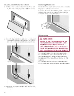
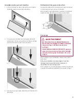
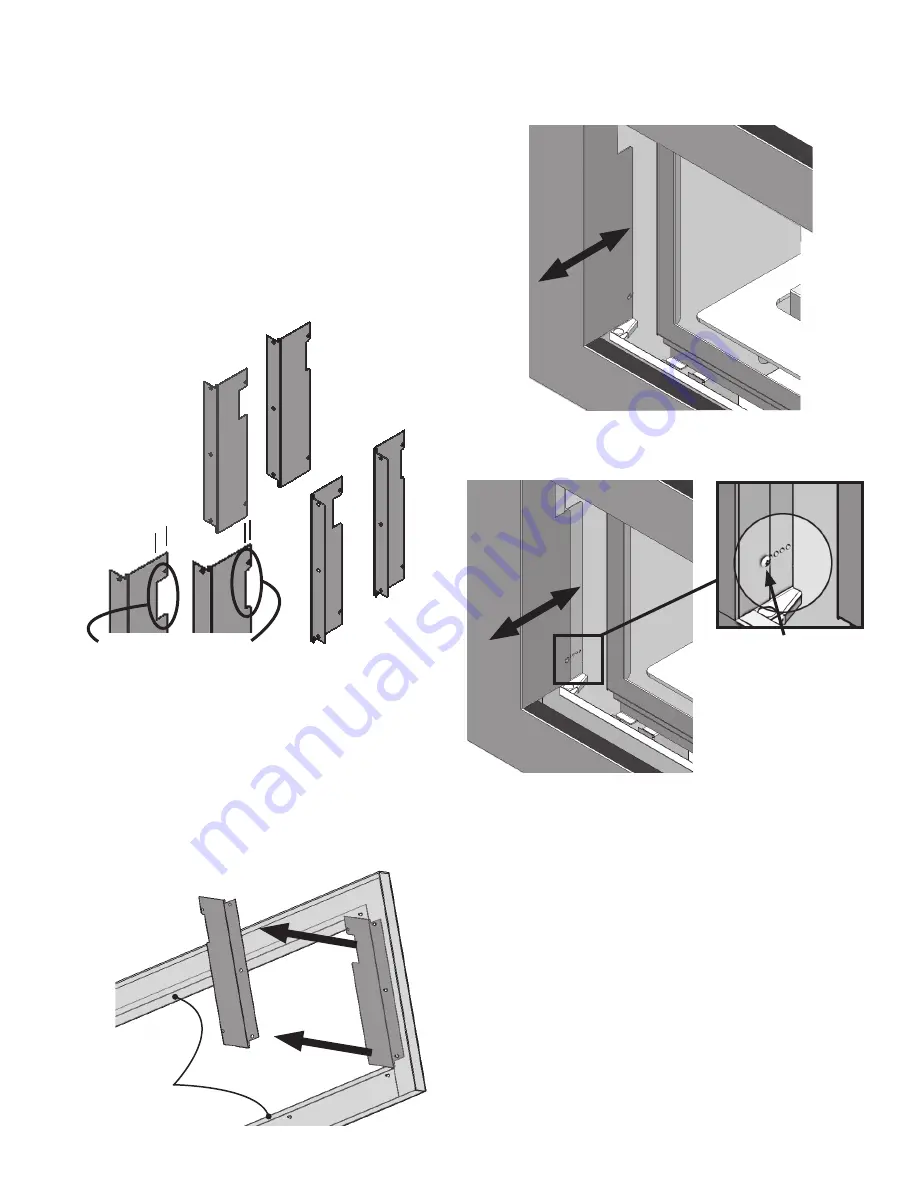
Installation
1. Locate trim inside perimeter of ‘window’ aperture
flanges, press firmly against finished face of wall.
2. Select a pre punched hole and secure trim using 4
no 8 screws.
Note: The metal
flange is wider at the
top of the trim than
at the bottom
Top
Bottom
fixing
screws (4)
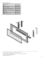
LH side
panels
RH side
pannels
0 - 1/2”,
panels ‘deep’
notch
1/2” - 1”, panels
‘shallow’ notch
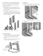
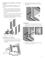
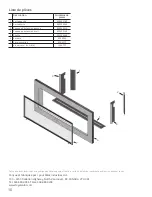
Considerations—Finish Wall Thickness
This trim can be adjusted according to the thickness
of the non-combustible wall finish. Two options of
installation can be used:
• Wall thickness on top of cement board of 0–1/2”.
For this option, the trim can be installed as it comes
out of the box. Follow installation steps in the next
section
Installation
.
• Wall thickness on top of cement board of 1/2”–1”.
For this option, the side panels on the trim must be
removed and the extension panels supplied with this
kit must be installed. Proceed to the following steps
before the installation.
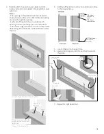
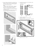
Trim Preparation
1. From the rear of the trim, remove the 6 fixing nuts
(3 per side) retaining the side panels to the trim.
Recycle these panels as they will no longer be
required.
2. Position the extension panels on the rear of the trim
and fix them with the 6 nuts (3 per side).


